<?xml version="1.0" encoding="ISO-8859-1"?><article xmlns:mml="http://www.w3.org/1998/Math/MathML" xmlns:xlink="http://www.w3.org/1999/xlink" xmlns:xsi="http://www.w3.org/2001/XMLSchema-instance">
<front>
<journal-meta>
<journal-id>2518-4431</journal-id>
<journal-title><![CDATA[Investigación & Desarrollo]]></journal-title>
<abbrev-journal-title><![CDATA[Inv. y Des.]]></abbrev-journal-title>
<issn>2518-4431</issn>
<publisher>
<publisher-name><![CDATA[UNIVERSIDAD PRIVADA BOLIVIANA]]></publisher-name>
</publisher>
</journal-meta>
<article-meta>
<article-id>S2518-44312020000100008</article-id>
<title-group>
<article-title xml:lang="en"><![CDATA[SLOPE STABILITY ANALYSIS BY FINITE ELEMENTS: A CASE STUDY IN LA PAZ-BOLIVIA]]></article-title>
<article-title xml:lang="es"><![CDATA[ANÁLISIS DE ESTABILIDAD DE TALUDES MEDIANTE EL EMPLEO DE ELEMENTOS FINITOS: UN CASO DE ESTUDIO EN LA PAZ - BOLIVIA]]></article-title>
</title-group>
<contrib-group>
<contrib contrib-type="author">
<name>
<surname><![CDATA[Gurruchaga R.]]></surname>
<given-names><![CDATA[Daniela]]></given-names>
</name>
<xref ref-type="aff" rid="A01"/>
</contrib>
<contrib contrib-type="author">
<name>
<surname><![CDATA[Viscarra A.]]></surname>
<given-names><![CDATA[Fabiana]]></given-names>
</name>
<xref ref-type="aff" rid="A01"/>
</contrib>
</contrib-group>
<aff id="A01">
<institution><![CDATA[,Universidad Privada Boliviana Facultad de Ingenierías y Arquitectura ]]></institution>
<addr-line><![CDATA[ ]]></addr-line>
</aff>
<pub-date pub-type="pub">
<day>00</day>
<month>00</month>
<year>2020</year>
</pub-date>
<pub-date pub-type="epub">
<day>00</day>
<month>00</month>
<year>2020</year>
</pub-date>
<volume>20</volume>
<numero>1</numero>
<fpage>99</fpage>
<lpage>111</lpage>
<copyright-statement/>
<copyright-year/>
<self-uri xlink:href="http://www.scielo.org.bo/scielo.php?script=sci_arttext&amp;pid=S2518-44312020000100008&amp;lng=en&amp;nrm=iso"></self-uri><self-uri xlink:href="http://www.scielo.org.bo/scielo.php?script=sci_abstract&amp;pid=S2518-44312020000100008&amp;lng=en&amp;nrm=iso"></self-uri><self-uri xlink:href="http://www.scielo.org.bo/scielo.php?script=sci_pdf&amp;pid=S2518-44312020000100008&amp;lng=en&amp;nrm=iso"></self-uri><abstract abstract-type="short" xml:lang="en"><p><![CDATA[The geomechanically analysis of slopes is one important application within the geotechnical engineering scope; this fact comprehends the evaluation of natural or artificial slope stability conditions. Such evaluation process can be optimized by means of modelling combined with engineer criteria. It is important to apply a mathematical model that focuses in the analysis objective and expected results; stress-strain methods allow determining the resistant and deformational parameters in a slope, being capable to reproduce its natural behavior [1]. The present research applies to a specific sector of La Paz city, named Villa Exaltación. The objective of this study is the performing of slope stability analysis through finite elements, in order to determine the areas that need remediation. The evaluation of stability alternatives it is also included. These alternatives go from simple remediation techniques (unstable material removal, slope undercut, inclination reduction, toe counterweight) to complex stabilization works such as pile curtains. The results reveal that a head slope undercut technique can bring stable conditions and minimal strain generation, being a satisfactory and feasible answer with low complexity works. Finally, verification was performed by means of limit equilibrium analysis. Both methodologies show satisfactory results, demonstrating that numerical methods are more representative and conservative. The calibration process of soil parameters plays a key role for the generation of a reliable model; critical conditions were simulated in order to determine minimal parameters needed for a stable slope.]]></p></abstract>
<abstract abstract-type="short" xml:lang="es"><p><![CDATA[Una aplicación importante de la ingeniería geotécnica es el análisis geomecánico de taludes que comprende el análisis de las condiciones de estabilidad de una ladera o talud artificial; este proceso puede ser optimizado a través de modelaciones, combinadas con el criterio del ingeniero. Dentro de las diferentes metodologías de modelación matemática, es importante emplear aquella que se enfoque en el objetivo del análisis y los resultados esperados, las modelaciones mediante métodos tensión-deformación permiten determinar los parámetros resistentes y deformacionales de una ladera, pudiendo reproducir el comportamiento real observado [1]. La presente investigación aplica a un sector específico de la ciudad de La Paz, denominado Villa Exaltación. El objetivo de este estudio radica en realizar un análisis de estabilidad de taludes mediante el método de elementos finitos para determinar las zonas donde sea necesaria la remediación. En este sentido, el estudio se complementa con análisis de alternativas de estabilización que permitan mejorar la estabilidad en curso de la zona de estudio. Dichas alternativas abarcan desde técnicas simples (remoción total de materiales inestables, corte de cabeza de talud, abatimiento de pendiente, contrapeso) hasta obras complejas de estabilización (cortina de pilotes). Los resultados revelan que, mediante un corte de cabeza de talud, se obtiene un factor de seguridad estable y deformaciones mínimas, demostrando de esta manera que es factible la implementación de obras civiles de baja complejidad, para obtener resultados satisfactorios. Finalmente se realizan verificaciones con métodos de cálculo simples basados en equilibrio límite. Los resultados, satisfactorios por ambas metodologías de cálculo, demuestran que los métodos numéricos son más representativos y además conservadores. Es importante considerar que el proceso de calibración de los parámetros del suelo, en un proceso significativo para generar una modelación numérica fiable; en el presente caso se simularon condiciones críticas para determinar los parámetros mínimos que brindarían sostenimiento al talud.]]></p></abstract>
<kwd-group>
<kwd lng="en"><![CDATA[Slope stability analysis]]></kwd>
<kwd lng="en"><![CDATA[slope]]></kwd>
<kwd lng="en"><![CDATA[finite elements]]></kwd>
<kwd lng="en"><![CDATA[Factor of Safety]]></kwd>
<kwd lng="en"><![CDATA[Limit Equilibrium]]></kwd>
<kwd lng="es"><![CDATA[Análisis de Estabilidad]]></kwd>
<kwd lng="es"><![CDATA[Taludes]]></kwd>
<kwd lng="es"><![CDATA[Elementos Finitos]]></kwd>
<kwd lng="es"><![CDATA[Factor de Seguridad]]></kwd>
<kwd lng="es"><![CDATA[Equilibrio Límite]]></kwd>
</kwd-group>
</article-meta>
</front><body><![CDATA[ <p><font color="#800000" size="2" face="Verdana, Arial, Helvetica, sans-serif"><b>DOI:</b> 10.23881/idupbo.020.1-8i</font></p>     <p align=right><font size="2" face="Verdana, Arial, Helvetica, sans-serif"><b>ART&Iacute;CULOS - INGENIER&Iacute;AS</b></font></p>     <p align=right>&nbsp;</p>     <p align=center><font size="4" face="Verdana, Arial, Helvetica, sans-serif"><b>SLOPE STABILITY ANALYSIS BY FINITE ELEMENTS: A CASE STUDY IN LA   PAZ-BOLIVIA</b></font></p>     <p align=center><font size="2" face="Verdana, Arial, Helvetica, sans-serif"><b>&nbsp;</b></font></p>     <p align=center><font size="3" face="Verdana, Arial, Helvetica, sans-serif"><b>AN&Aacute;LISIS DE ESTABILIDAD DE TALUDES MEDIANTE EL EMPLEO DE ELEMENTOS   FINITOS: UN CASO DE ESTUDIO EN LA PAZ &ndash; BOLIVIA</b></font></p>     <p align=center>&nbsp;</p>     <p align=center><font size="2" face="Verdana, Arial, Helvetica, sans-serif"><b>&nbsp;</b></font></p>     <p align=center><font size="2" face="Verdana, Arial, Helvetica, sans-serif"><b>Daniela Gurruchaga R., Fabiana Viscarra A.</b></font></p>     <p align=center><font size="2" face="Verdana, Arial, Helvetica, sans-serif"><i>Facultad de Ingenier&iacute;as y Arquitectura </i></font>    ]]></body>
<body><![CDATA[<br>     <font size="2" face="Verdana, Arial, Helvetica, sans-serif"><i>Universidad Privada Boliviana</i></font></p>     <p align=center><font size="2" face="Verdana, Arial, Helvetica, sans-serif"><a href="mailto:fabianaviscarra@upb.edu">fabianaviscarra@upb.edu</a></font></p>     <p align=center><font size="2" face="Verdana, Arial, Helvetica, sans-serif">(Recibido   el 29 de mayo 2020, aceptado para publicaci&oacute;n el 25 de junio 2020)</font></p>     <p align=center>&nbsp;</p>     <p align=center>&nbsp;</p> <hr align="JUSTIFY" noshade>     <p align="justify"><font size="2" face="Verdana, Arial, Helvetica, sans-serif"><b>ABSTRACT</b></font><font size="2" face="Verdana, Arial, Helvetica, sans-serif"><b>&nbsp;</b></font></p>     <p align="justify"><font size="2" face="Verdana, Arial, Helvetica, sans-serif">The geomechanically analysis   of slopes is one important application within the geotechnical engineering scope;   this fact comprehends the evaluation of natural or artificial slope stability   conditions. Such evaluation process can be optimized by means of modelling   combined with engineer criteria. It is important to apply a mathematical model   that focuses in the analysis objective and expected results; stress-strain   methods allow determining the resistant and deformational parameters in a   slope, being capable to reproduce its natural behavior [1]. The present   research applies to a specific sector of La Paz city, named Villa Exaltaci&oacute;n. The   objective of this study is the performing of slope stability analysis through   finite elements, in order to determine the areas that need remediation. &nbsp;The   evaluation of stability alternatives it is also included. These alternatives go   from simple remediation techniques (unstable material removal, slope undercut,   inclination reduction, toe counterweight) to complex stabilization works such   as pile curtains. The results reveal that a head slope undercut technique can   bring stable conditions and minimal strain generation, being a satisfactory and   feasible answer with low complexity works. Finally, verification was performed   by means of limit equilibrium analysis. Both methodologies show satisfactory   results, demonstrating that numerical methods are more representative and   conservative. The calibration process of soil parameters plays a key role for   the generation of a reliable model; critical conditions were simulated in order   to determine minimal parameters needed for a stable slope.</font><font size="2" face="Verdana, Arial, Helvetica, sans-serif"><b>&nbsp;</b></font></p>     <p align="justify"><font size="2" face="Verdana, Arial, Helvetica, sans-serif"><b>Keywords: </b>Slope stability analysis, slope, finite   elements, Factor of Safety, Limit Equilibrium.</font></p> <hr align="JUSTIFY" noshade>     <p align="justify"><font size="2" face="Verdana, Arial, Helvetica, sans-serif"><b>&nbsp;</b></font><font size="2" face="Verdana, Arial, Helvetica, sans-serif"><b>RESUMEN</b></font></p>     <p align="justify"><font size="2" face="Verdana, Arial, Helvetica, sans-serif">Una aplicaci&oacute;n importante de   la ingenier&iacute;a geot&eacute;cnica es el an&aacute;lisis geomec&aacute;nico de taludes que comprende el   an&aacute;lisis de las condiciones de estabilidad de una ladera o talud artificial;   este proceso puede ser optimizado a trav&eacute;s de modelaciones, combinadas con el   criterio del ingeniero. Dentro de las diferentes metodolog&iacute;as de modelaci&oacute;n   matem&aacute;tica, es importante emplear aquella que se enfoque en el objetivo del   an&aacute;lisis y los resultados esperados, las modelaciones mediante m&eacute;todos   tensi&oacute;n-deformaci&oacute;n permiten determinar los par&aacute;metros resistentes y   deformacionales de una ladera, pudiendo reproducir el comportamiento real   observado [1]. La presente investigaci&oacute;n aplica a un   sector espec&iacute;fico de la ciudad de La Paz, denominado Villa Exaltaci&oacute;n. El   objetivo de este estudio radica en realizar un an&aacute;lisis de estabilidad de   taludes mediante el m&eacute;todo de elementos finitos para determinar las zonas donde   sea necesaria la remediaci&oacute;n. En este sentido, el estudio se complementa con   an&aacute;lisis de alternativas de estabilizaci&oacute;n que permitan mejorar la estabilidad   en curso de la zona de estudio. Dichas alternativas abarcan desde t&eacute;cnicas   simples (remoci&oacute;n total de materiales inestables, corte de cabeza de talud,   abatimiento de pendiente, contrapeso) hasta obras complejas de estabilizaci&oacute;n   (cortina de pilotes). Los resultados revelan que, mediante un corte de cabeza   de talud, se obtiene un factor de seguridad estable y deformaciones m&iacute;nimas,   demostrando de esta manera que es factible la implementaci&oacute;n de obras civiles   de baja complejidad, para obtener resultados satisfactorios. Finalmente se   realizan verificaciones con m&eacute;todos de c&aacute;lculo simples basados en equilibrio l&iacute;mite.   Los resultados, satisfactorios por ambas metodolog&iacute;as de c&aacute;lculo, demuestran   que los m&eacute;todos num&eacute;ricos son m&aacute;s representativos y adem&aacute;s conservadores. Es   importante considerar que el proceso de calibraci&oacute;n de los par&aacute;metros del   suelo, en un proceso significativo para generar una modelaci&oacute;n num&eacute;rica fiable;   en el presente caso se simularon condiciones cr&iacute;ticas para determinar los   par&aacute;metros m&iacute;nimos que brindar&iacute;an sostenimiento al talud. </font></p>     ]]></body>
<body><![CDATA[<p align="justify"><font size="2" face="Verdana, Arial, Helvetica, sans-serif"><b>Palabras Clave: </b>An&aacute;lisis de Estabilidad, Taludes, Elementos   Finitos, Factor de Seguridad, Equilibrio L&iacute;mite.</font></p> <hr align="JUSTIFY" noshade>     <p align="justify"><font size="2" face="Verdana, Arial, Helvetica, sans-serif"><b>&nbsp;</b></font></p>     <p align="justify"><font size="2" face="Verdana, Arial, Helvetica, sans-serif"><b>&nbsp;</b></font></p>     <p align="justify"><font size="3" face="Verdana, Arial, Helvetica, sans-serif"><b>1. INTRODUCTION</b></font></p>     <p align="justify"><font size="2" face="Verdana, Arial, Helvetica, sans-serif">La Paz is considered as one   of the most vulnerable cities in Bolivia, in terms of landslides. Due to its   particular topography, unstable geological conditions and frequent human   intervention, people&acute;s safety and economy are compromised [2].   Villa Exaltaci&oacute;n is a sector of La Paz located in the   border region between the southeast area of El Alto city and the upper region   of the Alpacoma&rsquo;s river basin. According to the Risk Map (2011), Villa   Exaltaci&oacute;n presents a high-risk index, as a result of a moderate vulnerability level   and a high hazard range, due to its natural characteristics and surroundings   with the population [3].This sector is catalogued as high priority zone for   intervention. This paper therefore intends to analyze how critical the   stability is and how it can be improved through the modelling of stability   alternatives for hazard mitigation.</font></p>     <p align="justify"><font size="2" face="Verdana, Arial, Helvetica, sans-serif">In order to acquire the most   suitable solution, it is important to understand the mechanisms that have   generated or may generate potential slope failure. For such purpose, landslide   inventory and technical data collection with a chronological sequence are valuable   sources. Once slope failure mechanisms are understood, a method of analysis   that best fits the situation can be selected. Alternatives evaluation can   provide exact numerical values that may arise the solution feasibility. However,   it is important to remember that soil materials are highlighted by their degree   of complexity, which makes behavior prediction very difficult since these materials   are heterogeneous in space and depth. The use of a remediation technique should   be accompanied by an instrumentation or monitoring system that shall reduce   uncertainty and, finally, validate the adopted solution. Since these kinds of   systems are time and cost consuming, they are not often used.</font></p>     <p align="justify">&nbsp;</p>     <p align="justify"><font size="3" face="Verdana, Arial, Helvetica, sans-serif"><b>2. ANALYSIS METHODS FOR SLOPE STABILITY</b></font><font size="2" face="Verdana, Arial, Helvetica, sans-serif"><b>&nbsp;</b></font></p>     <p align="justify"><font size="2" face="Verdana, Arial, Helvetica, sans-serif">There are different methods   of analysis that can be used by geotechnical engineers to determine slope   stability conditions. These methods can be divided into three general groups: theoretical   (Closed form), simple and numerical analysis [4]. The difference between them relies   in the general solution&rsquo;s requirements that each one meets. It is fundamental   to acknowledge which of the four requirements are satisfied before considering   a specific method. These requirements are: equilibrium, compatibility, constitutive   behavior and boundary conditions [5].</font></p>     <p align="justify"><font size="2" face="Verdana, Arial, Helvetica, sans-serif">&#9632; Equilibrium has two components: global and internal   equilibrium. In the first one, forces and moments are associated throughout the   solution of their equations.&nbsp; In the second one, stresses must be stablished in   order to satisfy certain partial differential equations, which are:</font></p>     ]]></body>
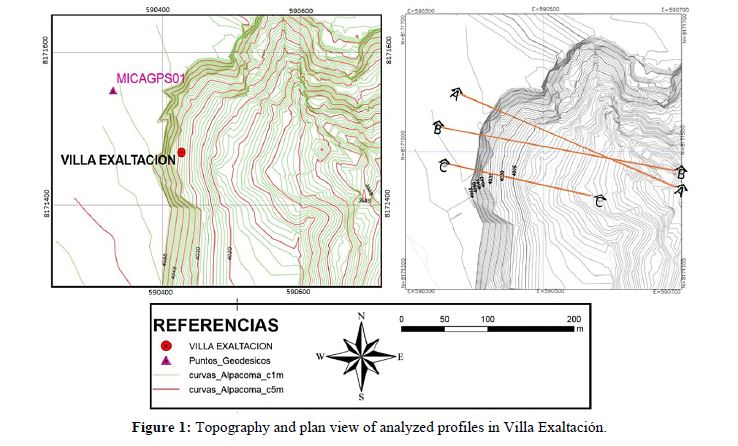
<body><![CDATA[<p align="center"><img src="/img/revistas/riyd/v20n1/n08_ecuacion_01.gif" width="748" height="123"></p>     <p align="justify"><font size="2" face="Verdana, Arial, Helvetica, sans-serif">where <img width=18 height=10 src="/img/revistas/riyd/v20n1/n08_ecuacion_01_01.gif">, <img width=19 height=11 src="/img/revistas/riyd/v20n1/n08_ecuacion_01_02.gif">, <img width=17 height=10 src="/img/revistas/riyd/v20n1/n08_ecuacion_01_03.gif">, <img width=19 height=11 src="/img/revistas/riyd/v20n1/n08_ecuacion_01_04.gif">, <img width=17 height=10 src="/img/revistas/riyd/v20n1/n08_ecuacion_01_05.gif">, and&nbsp;<img width=18 height=11 src="/img/revistas/riyd/v20n1/n08_ecuacion_01_06.gif">&nbsp;are the Cartesian components of total stresses.</font></p>     <p align="justify"><font size="2" face="Verdana, Arial, Helvetica, sans-serif">Former equation can be expressed as follows:</font></p>     <p align="center"><img src="/img/revistas/riyd/v20n1/n08_ecuacion_02.gif" width="752" height="42"></p>     <p align="justify"><font size="2" face="Verdana, Arial, Helvetica, sans-serif">where <img src="/img/revistas/riyd/v20n1/n08_ecuacion_02_01.gif" width="13" height="11">&nbsp;is the transpose of the differential operator defined as:</font></p>     <p align="center"><img src="/img/revistas/riyd/v20n1/n08_ecuacion_03.gif" width="735" height="123"></p>     <p align="justify"><font size="2" face="Verdana, Arial, Helvetica, sans-serif">Therefore, equilibrium is related to stresses &sigma;, mass   forces <i>&rho;b</i>&nbsp;and the inertial forces assembled in vector <i>&rho;<img src="/img/revistas/riyd/v20n1/n08_ecuacion_03_01.gif" width="8" height="11"></i>. In addition, density and the displacement vector are expressed as <i>&rho;</i>&nbsp;and </font><font size="2"><i>U</i></font><font size="2" face="Verdana, Arial, Helvetica, sans-serif">&nbsp;respectively.</font></p>     <p align="justify"><font size="2" face="Verdana, Arial, Helvetica, sans-serif">&#9632; Compatibility is associated with displacements and   strains. This requirement determines that holes or overlap between particles of   the material must not exist. In cases where strains are small, it is necessary   that the change of displacement throughout the body that has been analyzed must   satisfy the following condition: </font></p>     <p align="center"><img src="/img/revistas/riyd/v20n1/n08_ecuacion_04.gif" width="733" height="33"></p>     <p align="justify"><font size="2" face="Verdana, Arial, Helvetica, sans-serif">where <i>&epsilon;</i>&nbsp;is a vector that assembles strain elements and is related with the   displacement&rsquo;s element assembled in vector </font><font size="2"><i>U</i></font><font size="2" face="Verdana, Arial, Helvetica, sans-serif">.</font></p>     ]]></body>

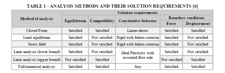
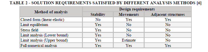
<body><![CDATA[<p align="justify"><font size="2" face="Verdana, Arial, Helvetica, sans-serif">&#9632; The Constitutive Behavior of a material provides a   correlation between the two requirements mentioned before as a result of the   stress-strain behavior of the material. This can be expressed with the   following constitutive equation:</font></p>     <p align="center"><img src="/img/revistas/riyd/v20n1/n08_ecuacion_05.gif" width="739" height="39"></p>     <p align="justify"><font size="2" face="Verdana, Arial, Helvetica, sans-serif">where &Delta;&sigma;&nbsp;and &Delta;<i>&epsilon;</i>&nbsp;represent the increments of stress and strain respectively, and </font><font size="2"><i>D</i></font><font size="2" face="Verdana, Arial, Helvetica, sans-serif">&nbsp;is the matrix in which the properties of soil are considered. This is   how the non-linear soil behavior is achieved, which is not considered in   methods of limit equilibrium.</font></p>     <p align="justify"><font size="2" face="Verdana, Arial, Helvetica, sans-serif">&#9632; Boundary Conditions represent the geotechnical problem   in question. The most important conditions are the imposed displacements,   static and/or dynamic applied loads, excavation and construction process, as   well as change in pore water pressure. </font></p>     <p align="justify"><font size="2" face="Verdana, Arial, Helvetica, sans-serif">A comparison between analysis   methods, and the fundamental theoretical requirements that they satisfy, are   presented in <a href="#t1">Table 1</a>.</font></p>     <p align="center"><a name="t1"></a><img src="/img/revistas/riyd/v20n1/n08_tabla_01.gif" width="736" height="241"></p>     <p align="justify"><font size="2" face="Verdana, Arial, Helvetica, sans-serif">The design requirements   depend on the selected method and can vary as shown in <a href="#t2">Table 2</a>.</font></p>     <p align="center"><a name="t2"></a><img src="/img/revistas/riyd/v20n1/n08_tabla_02.gif" width="728" height="184"></p>     <p align="justify"><font size="2" face="Verdana, Arial, Helvetica, sans-serif"><b>&nbsp;</b></font></p>     <p align="justify"><font size="3" face="Verdana, Arial, Helvetica, sans-serif"><b>3. NUMERICAL METHODS</b></font><font size="2" face="Verdana, Arial, Helvetica, sans-serif"><b>&nbsp;</b></font></p>     ]]></body>

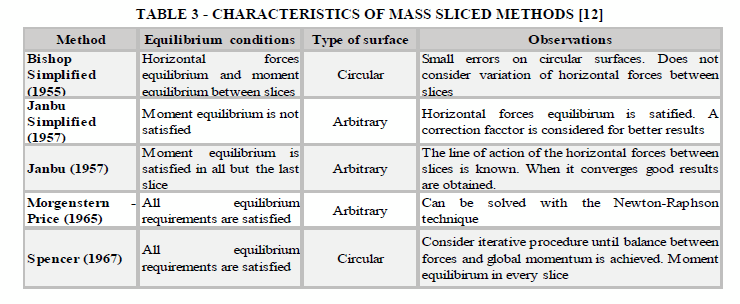
<body><![CDATA[<p align="justify"><font size="2" face="Verdana, Arial, Helvetica, sans-serif">Numerical methods can be   divided in three general groups: Continuum, Discontinuum and Hybrid methods. In   the first one, the geometric domain is managed by means of a discretization in   a finite number of elements. The solution is then obtained through numerical   approximations within differential equations. In discontinuum methods, the   geometric domain is managed as a set of interrelated discrete elements. This   method is generally used when fractured rock beds are studied. Finally, Hybrid   methods are used in rock engineering, where advantages of both methods   mentioned before can be applied [7]&nbsp;[5]. </font></p>     <p align="justify"><font size="2" face="Verdana, Arial, Helvetica, sans-serif"><b>Finite elements methods </b></font></p>     <p align="justify"><font size="2" face="Verdana, Arial, Helvetica, sans-serif">Finite Element Method (FEM) is   part of continuum methods and is used to determine the Factor of Safety (FOS)   by two possible procedures [8]: Direct and Improved Limit Analysis methods. In   the Direct analysis, slope stability can be evaluated with a shear strength reduction   technique or by means of superficial loads increments or mass loads   application. For the improved limit analysis, slope stability is determined   based on Limit Equilibrium Method (LEM) in addition to the finite element   method [9].</font></p>     <p align="justify"><font size="2" face="Verdana, Arial, Helvetica, sans-serif">This paper emphasizes the   shear strength reduction technique. For this purpose, parameters such as the   modulus of elasticity, Poisson&rsquo;s ratio and the dilation angle are needed,   besides conventional parameters used in LEM (e.g. internal friction angle and   cohesion). These additional parameters can be selected based on existing   tables, since the FOS determination is not affected if adopted parameters are   within an acceptable range [5]. The direct method offers the following benefits   and advantages compared to traditional analysis methods for slope stabilization   [9]&nbsp;[6]&nbsp;[10]:</font></p>     <p align="justify"><font size="2" face="Verdana, Arial, Helvetica, sans-serif">&#9632;&nbsp; Failure mechanism can be found without adopting a   failure surface shape or location. Failure mechanism shall develop along zones where   the material strength does not withstand the applied stresses.</font></p>     <p align="justify"><font size="2" face="Verdana, Arial, Helvetica, sans-serif">&#9632;&nbsp; Since the method of slices is not applicable,   interslice forces are not necessary.</font></p>     <p align="justify"><font size="2" face="Verdana, Arial, Helvetica, sans-serif">&#9632;&nbsp; By using real elasto-plastic parameters in the model, FEM   provides displacements and deformations values according to real stresses and   applied loads through construction process. </font></p>     <p align="justify"><font size="2" face="Verdana, Arial, Helvetica, sans-serif">&#9632;&nbsp; It is the most appropriate method in terms of   modelling progressive failures, for both, initial and final phase.</font></p>     <p align="justify"><font size="2" face="Verdana, Arial, Helvetica, sans-serif">&#9632;&nbsp; Complex stratigraphy can be easily modeled.</font></p>     <p align="justify"><font size="2" face="Verdana, Arial, Helvetica, sans-serif">It is possible to consider   the soil-structure interaction, in cases where reinforcement structures are   required.</font></p>     ]]></body>
<body><![CDATA[<p align="justify">&nbsp;</p>     <p align="justify"><font size="3" face="Verdana, Arial, Helvetica, sans-serif"><b>4. LIMIT EQUILIBRIUM METHODS </b></font><font size="2" face="Verdana, Arial, Helvetica, sans-serif"><b>&nbsp;</b></font></p>     <p align="justify"><font size="2" face="Verdana, Arial, Helvetica, sans-serif">LEM is based on a static   analysis between acting and resistant forces acting on a potentially unstable   soil mass. Due to their simplicity in comparison to stress-strain based   methods, it is known as a low cost and time consuming method, thereby it is   widely used. Within this method two categories can be distinguished [11].   The first is used only when the geometry of the slope is simple enough to be   considered as planar rupture and wedge rupture. In addition, it provides an   exact solution considering the absence of deformations and a constant FOS   throughout the entire failure surface. Thus, the global equilibrium is analyzed   considering a single sliding mass in homogeneous soils. The second category   tends to be hyperstatic due to the complexity of the geometry and requires some   simplification to obtain a solution. The second method divides the mass into   vertical slices so that each one has its respective two-dimensional equilibrium   analysis. This analysis can be performed on complex geometries with different   materials, external loads and interstitial pressures [11]. The method of slices   can be divided into precise and approximate methods. Approximate methods do not   satisfy all equilibrium equations, meanwhile the precise method does. The slice   methods used in this paper are presented in <a href="#t3">Table 3</a> according to their   different characteristics.</font></p>     <p align="center"><a name="t3"><img src="/img/revistas/riyd/v20n1/n08_tabla_03.gif" width="740" height="304"></a><font size="2" face="Verdana, Arial, Helvetica, sans-serif"><b>&nbsp;</b></font></p>     <p align="center">&nbsp;</p>     <p align="justify"><font size="3" face="Verdana, Arial, Helvetica, sans-serif"><b>5. FACTOR OF SAFETY</b></font><font size="2" face="Verdana, Arial, Helvetica, sans-serif"><b>&nbsp;</b></font></p>     <p align="justify"><font size="2" face="Verdana, Arial, Helvetica, sans-serif">FOS is used to determine the   level of threat for an exposed slope and considers its behavior under   unfavorable conditions. FOS is defined in various ways, most of them are based   on the equilibrium study of an element and the forces acting on it. Likewise,   it is defined as the relationship between the shear resistance of the existing   materials in the slope and the critical stresses produced by a potential   failure surface. This can be expressed as follows [13]:</font></p>     <p align="center"><img src="/img/revistas/riyd/v20n1/n08_ecuacion_06.gif" width="745" height="48"></p>     <p align="justify"><font size="2" face="Verdana, Arial, Helvetica, sans-serif">When it comes to circular surfaces where resistant and   acting moments are involved, the previous equation takes the form of:</font></p>     <p align="center"><img src="/img/revistas/riyd/v20n1/n08_ecuacion_07.gif" width="750" height="55"></p>     ]]></body>
<body><![CDATA[<p align="justify"><font size="2" face="Verdana, Arial, Helvetica, sans-serif">Most FOS analysis methods are   based on the Coulomb failure criterion, where an equilibrium is satisfied along   a given failure surface. This surface can be analyzed as a block or it can be   divided into slices, in which case the equation is analyzed for each of the divided   parts. As a result, the FOS equation can be expressed as:</font></p>     <p align="center"><img src="/img/revistas/riyd/v20n1/n08_ecuacion_08.gif" width="741" height="55"></p>     <p align="justify"><font size="2" face="Verdana, Arial, Helvetica, sans-serif">For FOS values less than one,   there is a possibility that the slope might collapse. For this reason, it is   recommended to adopt safety margins that provide a slope inclination defined by   a FOS greater than one. </font></p>     <p align="justify">&nbsp;</p>     <p align="justify"><font size="3" face="Verdana, Arial, Helvetica, sans-serif"><b>6. CASE OF STUDY</b></font></p>     <p align="justify"><font size="2" face="Verdana, Arial, Helvetica, sans-serif">When is about natural phenomena like landslides and   floods, La Paz is the most vulnerable city in the country, due to either   natural or socio-natural reasons. Its topography and soil composition, as well   as the uncontrolled growth of the urban area increases the seriousness of these   phenomena and can decrease the period of time between them [14].</font></p>     <p align="justify"><font size="2" face="Verdana, Arial, Helvetica, sans-serif">The area of the study is within the 41% of urban   sprawl, located inside moderate risk areas, which means that abrupt to moderate   natural slopes are present. It is also affected by superficial and internal   erosion, unstable sectors caused by the saturation and decrease of   physical-mechanical characteristics, and the presence of potentially active   fault zones [15].</font></p>     <p align="justify"><font size="2" face="Verdana, Arial, Helvetica, sans-serif">In 2011, the Municipal Autonomous Government of La Paz   (GAMLP) presented the Risk Map, determining which geographical areas presented   the possibility of adverse events. The Risk Map is based on natural   characteristics of the terrain, such as topography, geology, active geological   faults and soil geomechanically conditions and takes into account the social,   political or economic system that will be affected [15].</font></p>     <p align="justify"><font size="2" face="Verdana, Arial, Helvetica, sans-serif">According to the Risk Map, the area of Villa   Exaltaci&oacute;n presents a high geo-hazard level and a moderate level of   vulnerability, bearing in mind that the hazard is the combination of external   adverse factors caused by natural origins as a result of human intervention for   specific places; vulnerability could be considered as the situation in which a   population finds itself facing hazards [15].</font></p>     <p align="justify"><font size="2" face="Verdana, Arial, Helvetica, sans-serif">In June 2014, Antea Belgium   Group and Universidad Mayor de San Sim&oacute;n UMSS presented the results of a study   called &ldquo;Gesti&oacute;n Integral de la   Cuenca Alpacoma<i>&rdquo;</i> that was conducted from March to September   of 2013. The study comprises different analyses and tests within Alpacoma since   it has become a recurrent risk zone for the past 15 years.</font></p>     ]]></body>
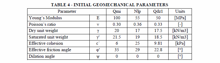
<body><![CDATA[<p align="justify"><font size="2" face="Verdana, Arial, Helvetica, sans-serif">Complementary studies were   also executed by the National Service of Geology and Mining (Sergeotecmin) in   2005, the Soil Mechanics Laboratory of UMSS in 2013 and Maldonado Exploraciones   in 2012.</font></p>     <p align="justify"><font size="2" face="Verdana, Arial, Helvetica, sans-serif"><b>6.1 Location</b></font></p>     <p align="justify"><font size="2" face="Verdana, Arial, Helvetica, sans-serif">The studied natural slope is   located in the southeast area of the city El Alto, on the border between the   area of Villa Exaltaci&oacute;n and the upper sector of Alpacoma&rsquo;s river basin,   covering an approximate extension of 6500 m<sup>2</sup>. The area has a cold   climate with temperatures below 0&deg;C and maximum precipitation between the   months of October and April, a period in which 90% of precipitation occurs. The   average of evaporation reveals that these are dry areas with high values of solar   radiation [3]. </font></p>     <p align="justify"><font size="2" face="Verdana, Arial, Helvetica, sans-serif"><b>6.2 Topography and   geology&nbsp;</b></font></p>     <p align="justify"><font size="2" face="Verdana, Arial, Helvetica, sans-serif">The topography is   characterized by the presence of well-defined scarps along the entire analyzed   profile in a constant and almost regular manner. For this reason, the decision   was made to conduct a representative analysis of three profiles. These profiles   are located at the beginning and end of the longitudinal scarp contour, and   where the least distance between the scarp and the adjacent avenue prevails.</font></p>     <p align="justify"><font size="2" face="Verdana, Arial, Helvetica, sans-serif">Regarding the geology of the   area, eight types of units can be distinguished. Three of them persist along   the profiles: <i>Formaci&oacute;n Milluni</i> (Qmi), <i>Formaci&oacute;n La Paz </i>(Nlp) and   a colluvium material unit defined as<i> Deslizamiento </i>(Qdzl). The first   strata is made up of poorly graded or well graded gravel on the slope border;   the second, characterized silty sand (SM) material and a combination of silty   sand and clayey sand (SM-SC) with sporadic levels of fine gravel and coarse   sand. Finally, the presence of colluvial deposits as a result of advanced   erosion. In addition, traction cracks were identified, acting as indicators of possible   active movements due slope instability.</font></p>     <p align="justify"><font size="2" face="Verdana, Arial, Helvetica, sans-serif"><b>6.3 Geotechnical studies conducted</b></font></p>     <p align="justify"><font size="2" face="Verdana, Arial, Helvetica, sans-serif">Collected information relevant to the area of study   includes sieve granulometry tests, Atterberg limits, hydrometer test and direct   shear tests. The tests mentioned were analyzed and supplemented in order to   obtain the initial geomechanical parameters needed to start the modeling   process in Plaxis. Geomechanical parameters adopted for each stratum are   presented in <a href="#t4">Table 4</a>.</font></p>     <p align="justify"><font size="2" face="Verdana, Arial, Helvetica, sans-serif">From this information it is determined that <i>Formaci&oacute;n   Milluni (Qmi) </i>is composed of granular materials, which are fundamentally   sandy gravel with bolts, presenting a low level of plasticity. On the other   hand, as it is a well-graded soil, it has an acceptable and favorable   permeability to carry out a long-term analysis under drained conditions.</font></p>     <p align="justify"><font size="2" face="Verdana, Arial, Helvetica, sans-serif">Tests reveal that <i>Formaci&oacute;n La Paz</i> (Nlp) soil&rsquo;s   composition consists mostly of low to medium plasticity clays, and also lesser   clayey and silty sands. According to its classification, this type of soil has   a regular permeability and workability. Additionally, information has been   collected from direct shear tests to obtain residual parameters since it is   close to Alpacoma River where traction cracks have been identified. </font></p>     ]]></body>
<body><![CDATA[<p align="justify"><font size="2" face="Verdana, Arial, Helvetica, sans-serif"><i>Material Deslizado </i>(Qzdl) consists of granular materials like   sandy gravel with pebbles and boulders. Moreover, their characteristics and   properties are similar to<i> Qmi</i>, therefore it can be deduced that this   material formed part of the mentioned unit before the material motion.</font></p>     <p align="center"><a name="t4"></a><img src="/img/revistas/riyd/v20n1/n08_tabla_04.gif" width="736" height="213"><font size="2" face="Verdana, Arial, Helvetica, sans-serif"><b>&nbsp;</b></font></p>     <p align="justify"><font size="2" face="Verdana, Arial, Helvetica, sans-serif"><b>&nbsp;</b></font></p>     <p align="justify"><font size="3" face="Verdana, Arial, Helvetica, sans-serif"><b>7. CALIBRATION OF   GEOMECHANICAL PARAMETERS</b></font></p>     <p align="justify"><font size="2" face="Verdana, Arial, Helvetica, sans-serif">Starting with initial   geomechanical values, final parameters are then calibrated in Plaxis. For this   purpose, A-A Profile is used for the base model process. In <a href="#f1">Figure 1</a>, the site   topography and delineated profiles are shown. </font></p>     <p align=center><a name="f1"></a><img src="/img/revistas/riyd/v20n1/n08_figura_01.jpg" width="738" height="446"></p>     <p align="justify"><font size="2" face="Verdana, Arial, Helvetica, sans-serif">Firstly, profile geometry was   introduced and then the stratums that compose the geometry were defined. Once   this information was introduced, geomechanical parameter values of each unit   were assigned. </font></p>     <p align="justify"><font size="2" face="Verdana, Arial, Helvetica, sans-serif">Next boundary condition is   water table delineation. Due to the limited information about the specific area   of analysis, an assessment was made upon the groundwater presence in <i>Tejada     Alpacoma </i>landslide, which is located 200 meters away from the area of the   study and presents the same geological units and similar soil composition.   Thus, the most critical situation for the slope analysis considers a 25 meter   depth water table that follows similar slope inclination.</font></p>     <p align="justify"><font size="2" face="Verdana, Arial, Helvetica, sans-serif">For the next step, three   calculation phases were defined:</font></p>     <p align="justify"><font size="2" face="Verdana, Arial, Helvetica, sans-serif">&#9632; The first, in which initial conditions are considered   by a plastic calculation and a type of load called <i>Total Multiplier</i>,   allows the software to provide the initial stresses of the soil. A linear   elastic model is assigned to the material, only for this phase.</font></p>     ]]></body>
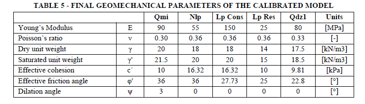
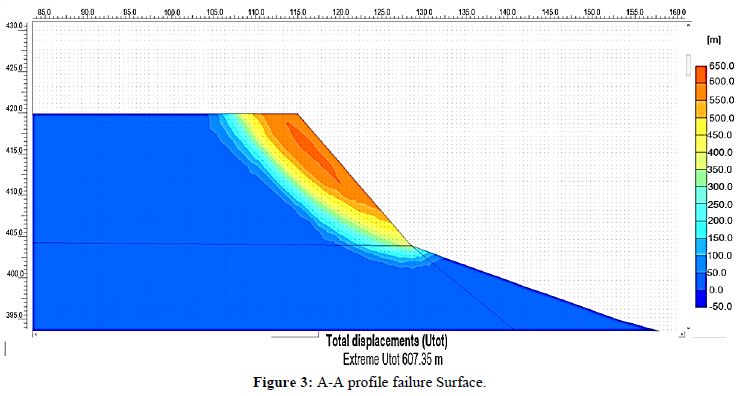
<body><![CDATA[<p align="justify"><font size="2" face="Verdana, Arial, Helvetica, sans-serif">&#9632; The second, which continues with a plastic calculation   and a type of load called <i>Staged Construction</i>, provides existing   deformations in the slope as a result. In this stage, Mohr Coulomb failure   model is applied.</font></p>     <p align="justify"><font size="2" face="Verdana, Arial, Helvetica, sans-serif">&#9632; The third and most important phase calculates FOS   values. In this phase, the <i>Phi/c reduction </i>method is assigned along with   a type of load called <i>Incremental Multipliers</i>.</font></p>     <p align="justify"><font size="2" face="Verdana, Arial, Helvetica, sans-serif">The iteration process involves   finding the geomechanical parameters that meet a FOS=1, simulating critical   conditions; therefore, these parameters would be the minimum ones that might make   the slope stable.</font></p>     <p align="justify"><font size="2" face="Verdana, Arial, Helvetica, sans-serif">During first iterations, geometry was adjusted in   order to obtain congruent boundary conditions for the initial model, increasing   the analysis depth in such a way that a stratum called <i>La Paz Consolidada</i> (Lp Cons) was introduced and defined. <i>La Paz Consolidada </i>represents the   conditions of a consolidated stratum considering the depth at which it is   located and adopts a modulus of elasticity slightly greater than Nlp.&nbsp; </font></p>     <p align="justify"><font size="2" face="Verdana, Arial, Helvetica, sans-serif">Due to traction cracks presence within the area, it is   assumed that a previous failure existed; thereby, part of the <i>Qmi</i> material was displaced and ended up forming the <i>Qdz1 </i>unit. Hence, the   stability problem focuses on <i>Nlp</i> strata and an additional stratum called <i>La Paz Residual </i>(Lp Res) is incorporated. Residual geomechanical   parameters are assumed for<i> Lp Res</i>. </font></p>     <p align="justify"><font size="2" face="Verdana, Arial, Helvetica, sans-serif">The cohesion for <i>Qmi </i>had to be slightly increased   since initial values did not represent the current stable situation of the   stratum.</font></p>     <p align="justify"><font size="2" face="Verdana, Arial, Helvetica, sans-serif">All of these adjustments were needed for the first   step of calibration, which focuses on finding the failure plane. Next step is   about redefining the failure surface by means of reducing soil parameters values.   In this way, the geomechanical parameters found are the minimum values that might   represent the current slope state.</font></p>     <p align="justify"><font size="2" face="Verdana, Arial, Helvetica, sans-serif">As previously established, <i>Nlp</i> and <i>Lp Res </i>parameters   were the most influenced after iterations; cohesion and friction angles are   considered the most important parameters for achieving the desired behavior of   the slope. After iterations, values changed depending on elasticity modulus;   going from very weak to very rigid clays. A quite low module of elasticity would   not match with the actual situation; furthermore, very high values dissolve the   possibility of any failure, then results were filtered until the minimum   relevant values were found according to slope expected behavior.&nbsp; </font></p>     <p align="justify"><font size="2" face="Verdana, Arial, Helvetica, sans-serif">A very important parameter   introduced during the final calibration phases is the dilation angle. Due to   the fact that <i>Qmi </i>is composed of granular soils and a shear deformation   exists, the soil expands, and the friction angle tends to be affected. In <a href="#t5">Table     5</a>, the results of the final parameters of the calibrated model are shown.</font></p>     <p align="center"><font size="2" face="Verdana, Arial, Helvetica, sans-serif"><a name="t5"></a><img src="/img/revistas/riyd/v20n1/n08_tabla_05.gif" width="739" height="211"></font></p>     ]]></body>
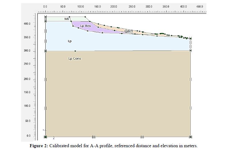
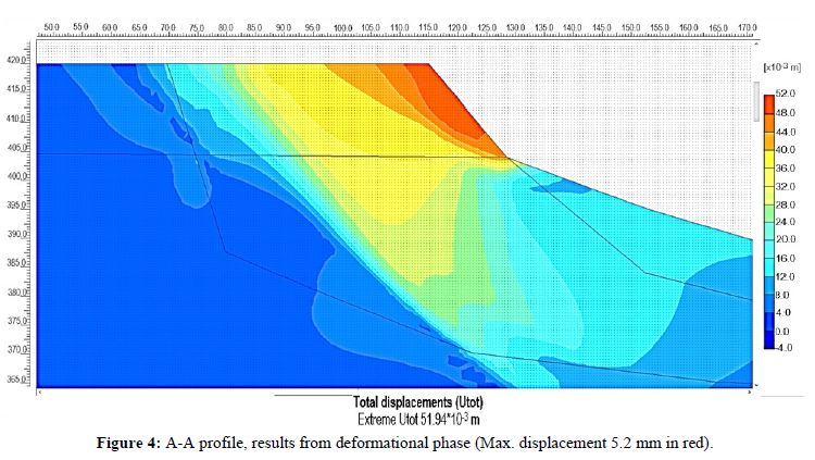
<body><![CDATA[<p align="justify"><font size="2" face="Verdana, Arial, Helvetica, sans-serif"><a href="#f2">Figure 2</a> shows the final geometry of the calibrated model in Plaxis that belongs to profile A-A.</font></p>     <p align="center"><a name="f2"></a><img src="/img/revistas/riyd/v20n1/n08_figura_02.jpg" width="732" height="486"></p>     <p align="justify"><font size="2" face="Verdana, Arial, Helvetica, sans-serif">With calibrated model of A-A   profile, FOS of 1.03 was obtained, <a href="#f3">Figure 3</a> displays the failure surface and <a href="#f4">Figure 4</a> the maximun displacements for the same profile. Maximum displacements   for A-A calibrated profile reached values of 5.2 mm. Once the calibration stage   was done, the evaluation of solution alternatives were the next step.</font></p>     <p align="center"><a name="f3"></a><img src="/img/revistas/riyd/v20n1/n08_figura_03.jpg" width="750" height="396"></p>     <p align="center">&nbsp;</p>     <p align="center"><a name="f4"></a><img src="/img/revistas/riyd/v20n1/n08_figura_04.jpg" width="750" height="423"></p>     <p align="justify"><font size="2" face="Verdana, Arial, Helvetica, sans-serif">Once the calibrated model   results were obtained, soil parameters were verified for both B-B and C-C   profiles by introducing each profile&rsquo;s geometry ans phreatic level. For these   profiles calibrated values from the different strata were used (<a href="#t2">Table 2</a>) for initial   modelling. </font></p>     <p align="justify"><font size="2" face="Verdana, Arial, Helvetica, sans-serif">A   FOS = 0.88 was obtained for the B-B profile along with a maximun displacement   of 2.57 cm under critical considerations with a high phreatic level and Lp Res   strata. These values exhibit that if critical conditions may remain, the slope   would not be capable to resist acting forces, leading to failure. A new   analysis was conducted under no-critical considerations in order to verify if   actual soil parameters give stability to the slope; thereby, FS=1.15 was   obtained as a result. </font></p>     <p align="justify"><font size="2" face="Verdana, Arial, Helvetica, sans-serif">Similar   behaviour was observed within C-C profile, where a FOS = 0.82 was obtained   under critical conditions along with 15.2 cm of total displacements. And FS=1,03,   total displacement of 1.9 cm were calculated by means of natural condition   verification.&nbsp; </font></p>     <p align="justify"><font size="2" face="Verdana, Arial, Helvetica, sans-serif">Once, the three calibrated   models were analysed under natural conditions, some posible solutions of   stability were studied.</font></p>     ]]></body>
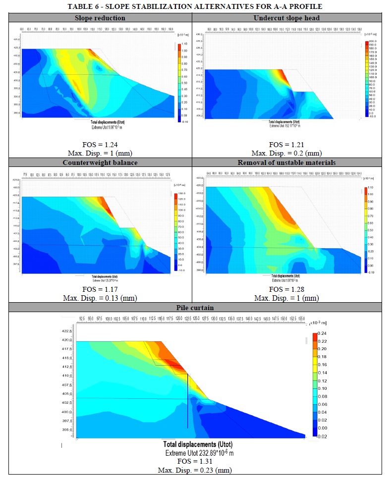
<body><![CDATA[<p align="justify">&nbsp;</p>     <p align="justify"><font size="3" face="Verdana, Arial, Helvetica, sans-serif"><b>8. STABILITY ALTERNATIVES</b></font></p>     <p align="justify"><font size="2" face="Verdana, Arial, Helvetica, sans-serif">The most suitable   stabilization methods are those that besides reaching slope stability are the   most economically efficient. As before mentioned, the evaluation zone is part of   priority stabilization sectors. There is a vast quantity of zones within   Alpacoma&rsquo;s river basin that needs analysis and remediation; for such purpose   simple up to complex remediation works were considered under the scope of this   study. Some characteristics were examined within the area: low population   downhill, low traffic in the upper part of the slope; the main scarp is   surrounded by a fence which is 8-meter distance from the scarp towards the   avenue. Besides, some watershed management works were observed such as plants   close to the toe zone. Residential structures are about 400 meter distance from   the toe.&nbsp; </font></p>     <p align="justify"><font size="2" face="Verdana, Arial, Helvetica, sans-serif"><b>8.1 A-A PROFILE</b></font></p>     <p align="justify"><font size="2" face="Verdana, Arial, Helvetica, sans-serif"><a href="#t6">Table 6</a> displays   deformational phases along with FOS results for the slope stabilization   analysis of different alternatives, modelled for A-A profile. </font></p>     <p align="center"><a name="t6"></a><img src="/img/revistas/riyd/v20n1/n08_tabla_06.jpg" width="787" height="977"></p>     <p align="justify"><font size="2" face="Verdana, Arial, Helvetica, sans-serif">Even though the five presented   alternatives (<a href="#t6">Table 6</a>) accomplished minimum safety values, only head undercut   and pile curtain were analyzed for B-B and C-C profiles. These are the reasons   why the other alternatives were not further considered:&nbsp; </font></p>     <p align="justify"><font size="2" face="Verdana, Arial, Helvetica, sans-serif">&#9632; Slope reduction might be an interesting alternative in   terms of reaching minimum FOS and deformations; nonetheless, new considerable   deformations were observed at a 15-meter span from the scarp. Thereby this   alternative was discarded.&nbsp; </font></p>     <p align="justify"><font size="2" face="Verdana, Arial, Helvetica, sans-serif">&#9632; Counter weight balance gives the least deformations   among the rest of the alternatives and a FOS &gt; 1; nevertheless, this   solution requires more resources to be implemented such as a top undercut and   the compaction of selected material to form a type of berm that will provide   the counterweight balance as toe support.</font></p>     <p align="justify"><font size="2" face="Verdana, Arial, Helvetica, sans-serif">&#9632; Unstable materials removal is a prevention method that   might be used is situations where is the only way to reduce the area   vulnerability. Due to the great material amount, product of excavation, this   alternative was discarded. </font></p>     ]]></body>
<body><![CDATA[<p align="justify"><font size="2" face="Verdana, Arial, Helvetica, sans-serif">For the slope undercut a 5   meter span is needed and materials shall be removed until 6 meter depth, giving   a geometry with 62&deg; inclination from the horizontal plane. </font></p>     <p align="justify"><font size="2" face="Verdana, Arial, Helvetica, sans-serif">Pile curtain for A-A profile   is composed by tangent piles with 1.2 m diameter and 16 meters length. The most   efficient location for placing the pile curtain is at the toe, by this means   piles will pass through the most competent strata. Concrete compressive   strength should be 210 Kg/cm<sup>2 </sup>along with other properties specified   in <a href="#t7">Table 7</a>.</font></p>     <p align="center"><a name="t7"></a><img src="/img/revistas/riyd/v20n1/n08_tabla_07.gif" width="742" height="151"></p>     <p align="justify"><font size="2" face="Verdana, Arial, Helvetica, sans-serif"><b>8.2 B-B Profile</b></font></p>     <p align="justify"><font size="2" face="Verdana, Arial, Helvetica, sans-serif">Once alternative stability   solutions were studied for A-A profile, then profile B-B response was analyzed   by means of critical conditions and considering the two above mentioned   alternatives.</font></p>     <p align="justify"><font size="2" face="Verdana, Arial, Helvetica, sans-serif">For slope undercutting within   B-B profile, a 5-meter span excavation is needed with 4-meter depth, reaching a   64&deg;slope.</font></p>     <p align="justify"><font size="2" face="Verdana, Arial, Helvetica, sans-serif">Regarding to the pile   curtain, it was determined that the optimum position was one meter deeper than   profile A-A location. Besides the contention line, undercutting will be needed   as well, at least a 3-meter wide and 4-meter depth cut from the scarp, in order   to reduce earth pressure over the curtain and slope stability.</font></p>     <p align="justify"><font size="2" face="Verdana, Arial, Helvetica, sans-serif">The results from the   deformational phase modeling are shown in <a href="#t8">Table 8</a> along with FOS values for   both alternatives.</font><font size="2" face="Verdana, Arial, Helvetica, sans-serif"><b>&nbsp;</b></font></p>     <p align="justify"><font size="2" face="Verdana, Arial, Helvetica, sans-serif"><b>8.3 Profile C-C</b></font></p>     <p align="justify"><font size="2" face="Verdana, Arial, Helvetica, sans-serif">The alternatives for C-C   profile were verified for the undercutting and pile curtain. It was determined   that a 5 meter wide and 8 meter depth excavation is needed at the top part, in   order to have a 63&deg; inclination referred to the horizontal plane. For the pile   curtain, optimum location is two meters deeper compared to profile A-A, a 3   meter wide by 4 meter depth excavation shall be needed at the head of the slope   for stability purposes. The results from the displacement phase calculus are   shown in <a href="#t8">Table 8</a> with respective FOS values.</font></p>     ]]></body>
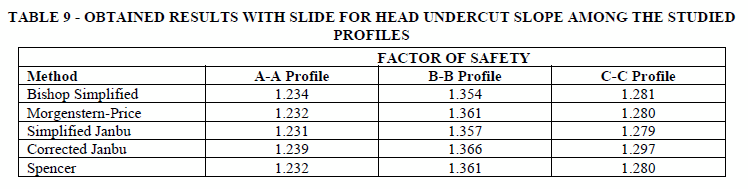
<body><![CDATA[<p align="center"><a name="t8"></a><img src="/img/revistas/riyd/v20n1/n08_tabla_08.gif" width="749" height="137"></p>     <p align="justify"><font size="2" face="Verdana, Arial, Helvetica, sans-serif">According to the results, it   is important to remark that maximum displacements were minimal and FOS values   were similar for both alternatives; thereby, the head undercut is the best   alternative since execution time and costs are less compared to the pile   curtain execution, this alternative accomplishes stabilization issues and   diminishes the sliding hazard in the zone. </font></p>     <p align="justify"><font size="2" face="Verdana, Arial, Helvetica, sans-serif">For B-B and C-C profiles,   displacements are also minimal; however, FOS is quite close to the permissible   FOS values but still slightly below 1.2. It is important to remark that Plaxis   modelling is more a strain-dependent slope stability method. Thus, verification   was complemented in accordance with Limit Equilibrium Method. </font></p>     <p align="justify">&nbsp;</p>     <p align="justify"><font size="3" face="Verdana, Arial, Helvetica, sans-serif"><b>9. VERIFICATION BY MEANS   OF LIMIT EQUILIBRIUM METHOD</b></font></p>     <p align="justify"><font size="2" face="Verdana, Arial, Helvetica, sans-serif">LEM is a widely used method   for soil stability analysis; thereby, FOS values were recalculated through   Bishop simplified, Morgenstern-Price, Janbu&rsquo;s Simplified, corrected Janbu and   Spencer methods, SLIDE software was used for such purpose.</font></p>     <p align="justify"><font size="2" face="Verdana, Arial, Helvetica, sans-serif">It is important to realize   that LEM method does not need a model calibration and requires less soil parameter&rsquo;s   information like cohesion, friction angle and bulk unit weights. For this   purpose, the used soil&rsquo;s parameters correspond to the calibrated parameters   applied in PLAXIS, for all the profiles.</font></p>     <p align="justify"><font size="2" face="Verdana, Arial, Helvetica, sans-serif">According to the Geotechnical   Manual for Slopes, the Spanish Edification Technique Code CTE [16]   and risk factors previously defined, Villa-Exaltacion slope presents a minor   life risk and low economical risk; thereby, the minimum FOS value shall be 1.2   in order to guarantee slope stability.</font></p>     <p align="justify"><font size="2" face="Verdana, Arial, Helvetica, sans-serif">LEM results for each profile   are shown in <a href="#t9">Table 9</a>. The modelled solution corresponds to the head undercut   slope, since this was the most optimal solution previously defined.</font></p>     <p align="center"><a name="t9"></a><img src="/img/revistas/riyd/v20n1/n08_tabla_09.gif" width="748" height="189"><font size="2" face="Verdana, Arial, Helvetica, sans-serif"><b>&nbsp;</b></font></p>     ]]></body>
<body><![CDATA[<p align="justify"><font size="2" face="Verdana, Arial, Helvetica, sans-serif"><b>&nbsp;</b></font></p>     <p align="justify"><font size="3" face="Verdana, Arial, Helvetica, sans-serif"><b>10. CONCLUSIONS</b></font></p>     <p align="justify"><font size="2" face="Verdana, Arial, Helvetica, sans-serif">Finite Element method was applied for Villa-Exaltacion   slope stability analysis. For this purpose, a calibration process was done   based on parameters reduction criteria. Initial adopted parameters were reduced   until failure was reached (FOS=1), by means of several iterations. According to   the soils&rsquo; characteristics, some behavior criteria were assumed in order to get   the failure plane and a successful calibration.</font></p>     <p align="justify"><font size="2" face="Verdana, Arial, Helvetica, sans-serif">Safety factors were calculated by means of real   conditions modelling after calibration, critical FOS values were 1.03, 0.88 and   0.82 within the three studied profiles. Thereby, mitigation works are precisely   needed since the sector is catalogued as high geo-hazard zone. Different   stabilization alternatives were analyzed, such as head undercut slope, removal   of unstable materials, counterweight at the toe and tangent piles curtain. It   is been deduced that deformation results are adequate (varying from 0.2 mm up   to 5.6 mm). In order to verify Plaxis results, Limit Equilibrium Method was   used, and FOS values were above 1.2, minimum value required from guidelines as   CTE. It was concluded that major complexity stabilization works might not be   needed since the head undercut slope would resolve stability problems. Thereby,   undercut slope is the most efficient stability solution compared to other   alternatives such as the implementation of tangent piles curtain.</font></p>     <p align="justify"><font size="2" face="Verdana, Arial, Helvetica, sans-serif">Numerical methods are characterized by focusing on   stress-strain reduction rather that FOS numerical value, representing a more   exact modelling method when slope analysis is needed. For the present study,   Finite Element method is merely based on the stress-strain response of the materials   giving more conservative and representative results, since this method is not   only based on statics analysis like LEM.</font></p>     <p align="justify">&nbsp;</p>     <p align="justify"><font size="3" face="Verdana, Arial, Helvetica, sans-serif"><b>11. REFERENCES</b></font></p>     <p align="justify"><font size="2" face="Verdana, Arial, Helvetica, sans-serif">[1] L. Gonz&aacute;lez de   Vallejo, M. Ferrer, . L. Ortu&ntilde;o y C. Oteo, Ingenier&iacute;a Geol&oacute;gica, Madrid,   Espa&ntilde;a: Pearson, 2002. </font></p>     <p align="justify"><font size="2" face="Verdana, Arial, Helvetica, sans-serif">[2] F. Viscarra,   &laquo;Slope Stability Analysis for Landslide Probability Mapping within Pampahasi   Zone, La Paz - Bolivia,&raquo; de <i>XV Panamerican Congress of Soil Mechanics and     Geotechnical Engineering Proceedings</i>, Buenos Aires - Argentina, 2015. </font></p>     <p align="justify"><font size="2" face="Verdana, Arial, Helvetica, sans-serif">[3] UMSS y Antea   Group, &laquo;Plan de manejo integral para la cuenca Alpacoma de Bolivia,&raquo; Tomo 4,   2015.</font></p>     ]]></body>
<body><![CDATA[<p align="justify"><font size="2" face="Verdana, Arial, Helvetica, sans-serif">[4] M. De Vos and   V. Whenham, &quot;Workpackage 3 Innovative design methods in geotechnical   engineering,&quot; Belgian Building Research Inst., GeoTechNet-European   Geotechnical Thematic Network.</font></p>     <p align="justify"><font size="2" face="Verdana, Arial, Helvetica, sans-serif">[5] J.   Bojorque-I&ntilde;eguez, &laquo;M&eacute;todos para el an&aacute;lisis de la estabilidad de pendientes,&raquo; <i>MASKANA, </i>vol. 2, n&ordm; 2, 2011. </font></p>     <p align="justify"><font size="2" face="Verdana, Arial, Helvetica, sans-serif">[6] D. Potts,   &laquo;Numerical analysis: a virtual dream or practical reality?,&raquo; <i>G&eacute;otechnique, </i>vol. 6, n&ordm; 535-573, p. 537, 2003. </font></p>     <p align="justify"><font size="2" face="Verdana, Arial, Helvetica, sans-serif">[7] E. Eberhardt,   D. Stead and J. Coggan, &quot;Numerical ana&ntilde;ysis of initiation and   progressive failure in natural rock slopes-the 1991 Randa rockslide,&quot; <i>International     Journal of Rock Mechanics and Mining Sciences, </i>vol. 41, no. 1, pp. 69-87,   2004. </font></p>     <!-- ref --><p align="justify"><font size="2" face="Verdana, Arial, Helvetica, sans-serif">[8] D. Naylor,   Numerical Methods in Geomechanics, Braga: Springer Netherlands, 1982. </font>&nbsp;&nbsp;&nbsp;&nbsp;&nbsp;&nbsp;&nbsp;&nbsp;[&#160;<a href="javascript:void(0);" onclick="javascript: window.open('/scielo.php?script=sci_nlinks&ref=976202&pid=S2518-4431202000010000800008&lng=','','width=640,height=500,resizable=yes,scrollbars=1,menubar=yes,');">Links</a>&#160;]<!-- end-ref --><p align="justify"><font size="2" face="Verdana, Arial, Helvetica, sans-serif">[9] T. Matsui and   K.-C. San, &quot;Finite Element Slope Stability Analysis by Shear Strength   Reduction Technique,&quot; <i>Soils and Foundations, </i>vol. 32, no. 1, pp.   59-70, March 1992. </font></p>     <p align="justify"><font size="2" face="Verdana, Arial, Helvetica, sans-serif">[10] H. Zheng, . D.   Liu and C. Li, &quot;Slope stability analysis based on elastoplastic finite   element method,&quot; <i>International Journal for Numerical Methods in     Engineering, </i>vol. 64, no. 14, 21 July 2005. </font></p>     <!-- ref --><p align="justify"><font size="2" face="Verdana, Arial, Helvetica, sans-serif">[11] Instituto   Geol&oacute;gico y Minero de Espa&ntilde;a (IGME), Manual de Taludes, 1987. </font>&nbsp;&nbsp;&nbsp;&nbsp;&nbsp;&nbsp;&nbsp;&nbsp;[&#160;<a href="javascript:void(0);" onclick="javascript: window.open('/scielo.php?script=sci_nlinks&ref=976205&pid=S2518-4431202000010000800011&lng=','','width=640,height=500,resizable=yes,scrollbars=1,menubar=yes,');">Links</a>&#160;]<!-- end-ref --><!-- ref --><p align="justify"><font size="2" face="Verdana, Arial, Helvetica, sans-serif">[12] E. A. P&eacute;rez,   &laquo;Estabilidad de Taludes,&raquo; Catalunya, 2005.</font>&nbsp;&nbsp;&nbsp;&nbsp;&nbsp;&nbsp;&nbsp;&nbsp;[&#160;<a href="javascript:void(0);" onclick="javascript: window.open('/scielo.php?script=sci_nlinks&ref=976206&pid=S2518-4431202000010000800012&lng=','','width=640,height=500,resizable=yes,scrollbars=1,menubar=yes,');">Links</a>&#160;]<!-- end-ref --><p align="justify"><font size="2" face="Verdana, Arial, Helvetica, sans-serif">[13] J. Suarez,   &laquo;Cap&iacute;tulo 4: An&aacute;lisis de Estabilidad,&raquo; de <i>Deslizamientos: An&aacute;lisis     Geotecnico</i>, Bucaramanga, Geotecnolog&iacute;a S.A.S., p. 130.</font></p>     ]]></body>
<body><![CDATA[<p align="justify"><font size="2" face="Verdana, Arial, Helvetica, sans-serif">[14] A. Cuevas,   &laquo;P&aacute;gina Siete, Diario Nacional Independiente,&raquo; 19 Enero 2019. [En l&iacute;nea].   Available: <a href="https://www.paginasiete.bo/sociedad/2014/1/19/anos-registro-menos-deslizamientos-11761.html" target="_blank">https://www.paginasiete.bo/sociedad/2014/1/19/anos-registro-menos-deslizamientos-11761.html</a>.   [&Uacute;ltimo acceso: 2 Octubre 2017].</font></p>     <!-- ref --><p align="justify"><font size="2" face="Verdana, Arial, Helvetica, sans-serif">[15] G. Sistema   Alerta Temprana Ante Inundaciones y Deliz, &laquo;Diagn&oacute;stico General del Sistema   de Alerta Temprana,&raquo; GAMLP, La Paz, 2011.</font>&nbsp;&nbsp;&nbsp;&nbsp;&nbsp;&nbsp;&nbsp;&nbsp;[&#160;<a href="javascript:void(0);" onclick="javascript: window.open('/scielo.php?script=sci_nlinks&ref=976209&pid=S2518-4431202000010000800015&lng=','','width=640,height=500,resizable=yes,scrollbars=1,menubar=yes,');">Links</a>&#160;]<!-- end-ref --><!-- ref --><p align="justify"><font size="2" face="Verdana, Arial, Helvetica, sans-serif">[16] Ministerio de   Vivienda de Espa&ntilde;a, &laquo;C&oacute;digo T&eacute;cnico de la Edificaci&oacute;n,&raquo; 2006.</font>&nbsp;&nbsp;&nbsp;&nbsp;&nbsp;&nbsp;&nbsp;&nbsp;[&#160;<a href="javascript:void(0);" onclick="javascript: window.open('/scielo.php?script=sci_nlinks&ref=976210&pid=S2518-4431202000010000800016&lng=','','width=640,height=500,resizable=yes,scrollbars=1,menubar=yes,');">Links</a>&#160;]<!-- end-ref --><p align="justify">&nbsp;</p>      ]]></body><back>
<ref-list>
<ref id="B1">
<label>1</label><nlm-citation citation-type="book">
<person-group person-group-type="author">
<name>
<surname><![CDATA[González de Vallejo]]></surname>
<given-names><![CDATA[L.]]></given-names>
</name>
<name>
<surname><![CDATA[Ferrer]]></surname>
<given-names><![CDATA[M.]]></given-names>
</name>
<name>
<surname><![CDATA[Ortuño]]></surname>
<given-names><![CDATA[L.]]></given-names>
</name>
<name>
<surname><![CDATA[Oteo]]></surname>
<given-names><![CDATA[C.]]></given-names>
</name>
</person-group>
<source><![CDATA[Ingeniería Geológica]]></source>
<year>2002</year>
<publisher-loc><![CDATA[Madrid, España ]]></publisher-loc>
<publisher-name><![CDATA[Pearson]]></publisher-name>
</nlm-citation>
</ref>
<ref id="B2">
<label>2</label><nlm-citation citation-type="confpro">
<person-group person-group-type="author">
<name>
<surname><![CDATA[Viscarra]]></surname>
<given-names><![CDATA[F.]]></given-names>
</name>
</person-group>
<source><![CDATA[Slope Stability Analysis for Landslide Probability Mapping within Pampahasi Zone, La Paz &#8211; Bolivia]]></source>
<year>2015</year>
<conf-name><![CDATA[ XV Panamerican Congress of Soil Mechanics and Geotechnical Engineering Proceedings]]></conf-name>
<conf-loc>Buenos Aires </conf-loc>
</nlm-citation>
</ref>
<ref id="B3">
<label>3</label><nlm-citation citation-type="">
<collab>UMSS</collab>
<collab>Antea Group</collab>
<source><![CDATA[Plan de manejo integral para la cuenca Alpacoma de Bolivia]]></source>
<year>2015</year>
</nlm-citation>
</ref>
<ref id="B4">
<label>4</label><nlm-citation citation-type="book">
<person-group person-group-type="author">
<name>
<surname><![CDATA[De Vos]]></surname>
<given-names><![CDATA[M.]]></given-names>
</name>
<name>
<surname><![CDATA[Whenham]]></surname>
<given-names><![CDATA[V.]]></given-names>
</name>
</person-group>
<source><![CDATA[Workpackage 3 Innovative design methods in geotechnical engineering]]></source>
<year></year>
<publisher-name><![CDATA[Belgian Building Research Inst., GeoTechNet-European Geotechnical Thematic Network]]></publisher-name>
</nlm-citation>
</ref>
<ref id="B5">
<label>5</label><nlm-citation citation-type="journal">
<person-group person-group-type="author">
<name>
<surname><![CDATA[Bojorque-Iñeguez]]></surname>
<given-names><![CDATA[J.]]></given-names>
</name>
</person-group>
<article-title xml:lang="es"><![CDATA[Métodos para el análisis de la estabilidad de pendientes]]></article-title>
<source><![CDATA[MASKANA]]></source>
<year>2011</year>
<volume>2</volume>
<numero>2</numero>
<issue>2</issue>
</nlm-citation>
</ref>
<ref id="B6">
<label>6</label><nlm-citation citation-type="journal">
<person-group person-group-type="author">
<name>
<surname><![CDATA[Potts]]></surname>
<given-names><![CDATA[D.]]></given-names>
</name>
</person-group>
<article-title xml:lang="en"><![CDATA[Numerical analysis: a virtual dream or practical reality?]]></article-title>
<source><![CDATA[Géotechnique]]></source>
<year>2003</year>
<volume>6</volume>
<page-range>535-573</page-range></nlm-citation>
</ref>
<ref id="B7">
<label>7</label><nlm-citation citation-type="journal">
<person-group person-group-type="author">
<name>
<surname><![CDATA[Eberhardt]]></surname>
<given-names><![CDATA[E.]]></given-names>
</name>
<name>
<surname><![CDATA[Stead]]></surname>
<given-names><![CDATA[D.]]></given-names>
</name>
<name>
<surname><![CDATA[Coggan]]></surname>
<given-names><![CDATA[J.]]></given-names>
</name>
</person-group>
<article-title xml:lang="en"><![CDATA[Numerical anañysis of initiation and progressive failure in natural rock slopes-the 1991 Randa rockslide]]></article-title>
<source><![CDATA[International Journal of Rock Mechanics and Mining Sciences]]></source>
<year>2004</year>
<volume>41</volume>
<numero>1</numero>
<issue>1</issue>
<page-range>69-87</page-range></nlm-citation>
</ref>
<ref id="B8">
<label>8</label><nlm-citation citation-type="book">
<person-group person-group-type="author">
<name>
<surname><![CDATA[Naylor]]></surname>
<given-names><![CDATA[D.]]></given-names>
</name>
</person-group>
<source><![CDATA[Numerical Methods in Geomechanics]]></source>
<year>1982</year>
<publisher-loc><![CDATA[Braga ]]></publisher-loc>
<publisher-name><![CDATA[Springer Netherlands]]></publisher-name>
</nlm-citation>
</ref>
<ref id="B9">
<label>9</label><nlm-citation citation-type="journal">
<person-group person-group-type="author">
<name>
<surname><![CDATA[Matsui]]></surname>
<given-names><![CDATA[T.]]></given-names>
</name>
<name>
<surname><![CDATA[San]]></surname>
<given-names><![CDATA[K.-C.]]></given-names>
</name>
</person-group>
<article-title xml:lang="en"><![CDATA[Finite Element Slope Stability Analysis by Shear Strength Reduction Technique]]></article-title>
<source><![CDATA[Soils and Foundations]]></source>
<year>Marc</year>
<month>h </month>
<day>19</day>
<volume>32</volume>
<numero>1</numero>
<issue>1</issue>
<page-range>59-70</page-range></nlm-citation>
</ref>
<ref id="B10">
<label>10</label><nlm-citation citation-type="journal">
<person-group person-group-type="author">
<name>
<surname><![CDATA[Zheng]]></surname>
<given-names><![CDATA[H.]]></given-names>
</name>
<name>
<surname><![CDATA[Liu]]></surname>
<given-names><![CDATA[D.]]></given-names>
</name>
<name>
<surname><![CDATA[Li]]></surname>
<given-names><![CDATA[C.]]></given-names>
</name>
</person-group>
<article-title xml:lang="en"><![CDATA[Slope stability analysis based on elastoplastic finite element method]]></article-title>
<source><![CDATA[International Journal for Numerical Methods in Engineering]]></source>
<year>21 J</year>
<month>ul</month>
<day>y </day>
<volume>64</volume>
<numero>14</numero>
<issue>14</issue>
</nlm-citation>
</ref>
<ref id="B11">
<label>11</label><nlm-citation citation-type="">
<collab>Instituto Geológico y Minero de España (IGME)</collab>
<source><![CDATA[Manual de Taludes]]></source>
<year>1987</year>
</nlm-citation>
</ref>
<ref id="B12">
<label>12</label><nlm-citation citation-type="">
<person-group person-group-type="author">
<name>
<surname><![CDATA[Pérez]]></surname>
<given-names><![CDATA[E.A.]]></given-names>
</name>
</person-group>
<source><![CDATA[Estabilidad de Taludes]]></source>
<year>2005</year>
<publisher-loc><![CDATA[Catalunya ]]></publisher-loc>
</nlm-citation>
</ref>
<ref id="B13">
<label>13</label><nlm-citation citation-type="book">
<person-group person-group-type="author">
<name>
<surname><![CDATA[Suarez]]></surname>
<given-names><![CDATA[J.]]></given-names>
</name>
</person-group>
<article-title xml:lang="es"><![CDATA[Capítulo 4: Análisis de Estabilidad]]></article-title>
<source><![CDATA[Deslizamientos: Análisis Geotecnico]]></source>
<year></year>
<page-range>130</page-range><publisher-loc><![CDATA[Bucaramanga ]]></publisher-loc>
<publisher-name><![CDATA[Geotecnología S.A.S.]]></publisher-name>
</nlm-citation>
</ref>
<ref id="B14">
<label>14</label><nlm-citation citation-type="book">
<person-group person-group-type="author">
<name>
<surname><![CDATA[Cuevas]]></surname>
<given-names><![CDATA[A.]]></given-names>
</name>
</person-group>
<source><![CDATA[X]]></source>
<year>19 E</year>
<month>ne</month>
<day>ro</day>
<publisher-name><![CDATA[Página Siete, Diario Nacional Independiente]]></publisher-name>
</nlm-citation>
</ref>
<ref id="B15">
<label>15</label><nlm-citation citation-type="book">
<collab>G. Sistema Alerta Temprana Ante Inundaciones y Deliz</collab>
<source><![CDATA[Diagnóstico General del Sistema de Alerta Temprana]]></source>
<year>2011</year>
<publisher-loc><![CDATA[La Paz ]]></publisher-loc>
<publisher-name><![CDATA[GAMLP]]></publisher-name>
</nlm-citation>
</ref>
<ref id="B16">
<label>16</label><nlm-citation citation-type="">
<collab>Ministerio de Vivienda de España</collab>
<source><![CDATA[Código Técnico de la Edificación]]></source>
<year>2006</year>
</nlm-citation>
</ref>
</ref-list>
</back>
</article>