ARTÍCULOS – INGENIERÍAS
DESIGNING AND DEVELOPMENT OF A DYNAMIC VIBRATION BALANCING MACHINE FOR INDUSTRIAL APPLICATIONS
DISEÑO Y DESARROLLO DE UNA MÁQUINA DE BALANCEO DINÁMICO DE VIBRACIONES PARA APLICACIONES INDUSTRIALES
Swith Claude Burgos Alconz and Grover Zurita V.
Laboratorio de Innovación Tecnológica Industrial y Robótica (LITIR) ]]>
Universidad Privada Boliviana(Recibido el 05 junio 2019, aceptado para publicación el 28 junio 2019)
ABSTRACT
There is a steadily growing demand for reliable, versatile measurement rotor balancing system which can be used to determine the machine unbalances behavior. The effect of these causes are the increase of vibration amplitudes, causing damage to elements of the machines, mainly in the bearings, reduce useful life time, and increase fatigue failure in machines. The industry requires that machines have to operate continuously, efficient maintenance philosophy, and reduce down time. Therefore, this research work has the main objective to design and develop a low cost rotor balancing measurement system for industrial applications. This research study was based on the ISO 1940-1 standard. The Solidworks software was used for the designing, structural stress, and modal analysis. It was also carried out and extensive numerical analysis with Finite Element Method (FEM), of the developed measurement system, in order to identify the structure resonance frequencies to avoid with the induction motor rotation frequency. For the simplicity, precision and robustness, the single plane four runs method for rotor balancing was selected. Finally, it was developed a rotor balancing measurement system. It showed the ability, and potential to use the developed equipment in industrial environment. Moreover, it has been shown that the measurement and the applied analysis method have worked accurate for unbalance detection and reduction of vibration levels from G13 to G2.
Keywords: Rotor, Balancing, Vibration analysis, Solidworks, FEM, Modal Analysis, ISO 1940-1.
RESUMEN
]]> Existe una creciente demanda de un sistema de balanceo de rotores de medición fiable y versátil que se pueda utilizar para determinar el comportamiento de desequilibrio de los equipos. El efecto del desbalanceo causa el aumento de las amplitudes de vibración, generando daños a los elementos de las máquinas, principalmente en los rodamientos, reduce la vida útil, y aumenta la falla de fatiga en las máquinas. La industria requiere que las máquinas operen continuamente, la filosofía es de un mantenimiento eficiente y pueda reducirse el tiempo de inactividad de los equipos. Por tanto, este trabajo de investigación tiene el objetivo principal de diseñar y desarrollar un sistema de medición de desbalanceo de rotores de bajo costo, mediante análisis vibracional para aplicaciones industriales. El desarrollo del sistema de medición se basa en la normativa de ISO 1940-1. El análisis de resistencia de materiales y el análisis dinámico de análisis de modos fue realizado en el software Solidworks. El estudio de las características dinámicas del equipo desarrollado, se pudo determinar con análisis modal, con el fin de identificar las frecuencias de resonancia de la estructura diseñada, esto para evitar la frecuencia de rotación del motor de inducción. En base a la bibliografía estudiada, el método de análisis para identificar la masa de desbalance y distancia, fue realizado con análisis vibracional y el método de cuatro corridas de plano único para el equilibrio del rotor. Finalmente, se desarrolló un sistema de medición de desbalance de rotores, de precisión y con potencial para utilizar el equipo en el entorno industrial. Se ha demostrado que las mediciones de análisis vibracional y el método de detección de desbalanceo, han funcionado con precisión para la detección de desequilibrios y la reducción de los niveles de vibración de G13 a G2.Palabras Clave: Rotor, Desequilibrio, Análisis Vibracional, Solidworks, FEM, Análisis Modal, ISO 1940-1.
The unbalance is consider the most common source of vibration in machine components [1], [2]. It could cause for excessive bearings loadings, which reduce useful life time, and increase fatigue failure of machines. In modern machines, the unbalance factor is quite important for designing and maintenance health monitoring. Based on the aforementioned, there is a need to have industrial equipment in continuous operation, and the best way to increase the machines life time are through its adequate alignment and precision balancing methods. If the machine is balanced and aligned correctly, and if all the resonance problems are corrected, then it is likely that the machine will operate for a significantly longer time period, before failures occurs[3], [4]. Any type of failure mode can lead to a functional failure and therefore to economic losses. Therefore, in order to secure an efficient working machines process [5],[6],[7], in recent years have been applying efficiently, the conditions maintenance approach.
The literature review showed that the most common faults in rotating machines are due to misaligned axes and unbalanced rotors (2). Therefore, in this context, the development of balancing machines for industrial applications is of mayor significance. Due to the characteristics of this research project, the literature survey covers two main parts: a) Design and development of rotor balancing systems, and b) Rotor balancing quantification techniques.
S. Sweedney et al., in 2005 [8] redesigned the rotor balancing system to reduce the unbalance phenomena. It was obtained by changing a lighter disk and shorter rotor shaft to increase the rigidly of the system. D. Han in 2006 [9], developed a model balancing for non-isotropic rotor system. The idea was to develop a generalized modal analysis from an unbalance model response to obtain new model parameters to be use partly, to quantify the unbalances, and partly to reduce it. L. T. Hongwei et al., in 2011[10], their research work was based on vibration signals analysis and filtering techniques. They developed an online process for dynamic balancing system for spindle and grinding in CNC machines.
A laser device was implemented to perform rotor balancing by, M. Stoesslein et al., in 2016. It works by the laser removing materials in automatic and controlled form. A structure surface vibration signals values were used to activate removing materials. A. Wanq et al., in 2017 [10], applied a four order non-homogeneous partial differential equation set to unbalance responses, damping bearing coefficients and rotor unbalance. It was also proposed a novel measurement Point Vector Method to determine rotor unbalance under operating. A high speed balance approach was developed for turbo machinery by G. Bin in 2018. The rotating speed of a rotor is hardly constant in practice due to angular speed fluctuation, which affects the balancing accuracy of the rotor. In this paper, the effect of angular speed fluctuation on vibration responses of the unbalanced rotor is analyzed quantitatively. Then, a vibration signal correction method based on zoom synchro’s squeezing transform (ZST) and tacho less order tracking was proposed. The instantaneous angular speed (IAS) of the rotor is extracted by the ZST firstly and then used to calculate the instantaneous phase. The vibration signal is further resampled in angular domain to reduce the effect of angular speed fluctuation. The signal obtained in angular domain is transformed into order domain using discrete Fourier transform (DFT) to estimate the amplitude and phase of the vibration signal. Simulated and experimental results show that the proposed method can successfully correct the amplitude and phase of the vibration signal due to angular speed fluctuation. The Coefficient Balance Method (CBM) was used to identify the shaft balancing values. The multi plane coefficients with varying speeds are based on steady state response from the Finite Element Method (FEM).
H. Cao, et al., in 2018 [11], studied the vibration signal corrections of an unbalanced rotor as a result of speed fluctuations. First, it was defined the speed fluctuations and it was reduced the effects of the rotors fluctuations, by using the Zoom Synchrosqueezing Transform (ZST). A self-sensing piezoelectric actuator was used for unbalance detection in rotor systems, by R. Ambur, et al., in 2018 [12]. In this research, the tests were performed the unbalance rotor faults were detected by using a parameter optimization method, which was also calculated the location, phase and unbalance magnitude. The final analysis was performed in laboratory test bench, and the developed method could be used both for control action and fault detection. It was also described included a numerical simulation of the manufactured prototype and it was also performed a dynamical structure analysis by modal analysis.
]]> The literature review reveals that an extensive research has been performed; partly study the development and designing of rotor balancing system and the use of different measurement techniques to detect the unbalance severity. However, it can be stated it has still a place to research in this field partly, to give a systematic framework for rotor unbalance quality measurements. Therefore, the main objective of this research work was to design and developed a low cost dynamic rotor balancing machine. It`s recommend the condition based-maintenance (MBC), which is a maintenance program to collect data continuously and perform the maintenance decisions [13], [14], [15], [16], [17].
2. THEORETICAL BACKGROUND: ROTOR BALANCING THEORY, STRUCTURE STRESS ANALYSIS AND MODAL ANALYSIS
2.1 Rotor Balancing Theory
The unbalance is defined as, the condition that exists in a rotor when vibratory forces are imparted to its bearings as a result of the existence of centrifugal forces. The presence of imbalance causes a centrifugal force which is proportional to the square of the rotational speed or angular frequency. The following equation sustains the above.
![]()
where ![]() is the centrifugal force in newton
is the centrifugal force in newton ![]() , m is the unbalance mass, e is the distance between the central shaft rotation with the unbalance mass, and
, m is the unbalance mass, e is the distance between the central shaft rotation with the unbalance mass, and ![]() is the rotor angular velocity.
is the rotor angular velocity.
Figure 1 shows a typical mass-spring system, restricted for vertical movements "x" and excited by a rotating machine that is unbalanced. The unbalance is represented by a mass (m) that causes an eccentricity, and an unbalance force in the radial direction.
Figure 1: Spring –mass system with unbalance mass (m)[18].
]]> The distribution mass of a rotor is checked and, if necessary, adjusted to predict that the residual unbalance or vibration of the bearings and/or the force in the bearings at a frequency corresponding to the speed service are within the specified limits [5]. By reading the above definition it can be implied that there is a maximum allowable unbalance for each rotating component, see even the IS0 1940-1 for details. The maximum admissible unbalance can vary for different operating conditions [6]. To balance a rotor, it is necessary to apply a distribution of forces in such a way as to counteract the sum of the centrifugal forces resulting from the unbalance of each plane.The rotor balancing can be performed in two ways, which are, "in-situ" and "in workshop". The first one refers to performing the balancing in the field i.e. balancing the rotating machine in its working place. The second alternative, refers to removing the rotor from the working place and taking it to a test bench [7]. Each aforementioned method form has its advantages/disadvantages, the technique to be applied will depend mainly on the size of the rotor, the access for taking measurements, safety to the personnel and adjacent machines that could cause noise when taking readings.
Figure 2 illustrates a high peak (vibration amplitude) of about the first order at the rotation frequency of the rotor. It is said that the rotor is unbalanced if the obtained vibration amplitudes are above the permitted threshold, see even the ISO 1940-1 for details. The general idea is to reduce considerably the vibration peaks at the frequency of rotation in order to avoid unbalance of a rotor [8]. The rotor unbalance increment is not linear but increases proportionally to the square of the angular velocity.
.
Figure 2: Waterfall spectrums with frequency orders with increasing content of unbalances[19].
There are four types of rotor balancing methods: a) Single plane balance method, b) Couple par, c) Quasi- static and d) Dynamical unbalance (Multiple plane balance). Based on the literature review, it was defined to develop in our research work the single plane balanced method. The 95% of the unbalance machines can be handled by the aforementioned method (9). It can be introduced a general idea how it works. Figure 3 shows a rotor in two supports and an unbalance mass causing the main axis of inertia to move away from the principal axis of rotation.
Figure 3: Rotor with additional mass and two main supports.
In Figure 3 F1 is the centrifugal force and m1 is the unbalance mass. When the unbalanced mass is in a singular plane, as in the case of a fan rotor (thin), the resulting unbalance is a radial force (F1). Figure 4 shows how the unbalance can be corrected by placing a correction mass in the opposite direction to the unbalance.
|
|
|
Figure 4: a) Rotor with unbalance mass, b) Rotor with correction mass [20].
In IRD Mechanalysis [21], defined the criteria for choosing the number of correction planes in rigid rotors. They observed that balancing in a single plane method is usually sufficient for rotors with length (L) /Diameter(D) and the ratio of less than 0.5 and speed range up to 1000 rpm.
Figure 5a) shows increasing speeds doesn`t changed the unbalanced in a rigid rotor. The unbalance will remain approximately constant when the rotor is working at its operating speed [22]. The unbalance is both constant in the Cartesian and the polar plane, respectively
Figure 5: Behavior of a changing speed rotor, a) Rigid rotor and b) flexible rotor.
In Figure 5 na is the low rotating speed, and nb is the operational speed. Figure 5 b) illustrates the behavior of a flexible rotor. It can be seen that the rotor unbalance changes values with increasing speed [22].
2.2 Structure Stress Analysis and Dynamical Modal analysis
The developed rotor balancing measurement system was analyzed by the Finite Element Method (FEM), based on the Von Misses Equation. The solid works software (Dynamic module) was applied for the stress and the modal analysis. The general Von Misses equation is [23]:
]]>
3. DESIGN AND CONSTRUCTION OF THE ROTOR BALANCING MACHINE
Figure 6 shows a typical balancing machine where the unit of measurement and the element (rotor) to be analyzed is on a bench. There are bearing supports that are suspended on the pedestal and it has the possibility to move horizontally, and their heights are adjusted according to the rotor diameter axis.
Vibratory dampers are added to avoid resonance in the structure. Vibration sensors are attached to the supports for data vibration recording. The universal machines refer to horizontal axis machines and the single-purpose balancing machines can be vertical and horizontal according to the task to be fulfilled.
|
| |
| Figure 6: | Overview of a universal balancing machine. 1) Base or bench, 2) Pedestals, 3) Drive, 4) Sensors, 5) Measurement units (3). |
To be systematic and optimize the designing and manufacturing process of the rotor balancing measurement system all the process was based on [23], and sketched as shown in Figure 7. It starts with the requirement needs and identification of the problem. The project had to synthesis, structuring the tasks to perform. After many iterations, it ends with the presentation of the plans to satisfy the need. Depending on the nature of the design task, some phases of design may be repeated during the life of the product, from conception to completion [14].
Figure 7: Design process phases [14].
3.1 Relevant Balancing Aspects
]]> Balancing is a process by which the mass distribution of a rotor is monitored. It is necessary to ensure that the unbalance of the machine is within specified limits. Rotor unbalance can be caused by manufacturing, design, material, and assembly faults. Every rotor has an individual unbalance distribution along its length and diameter. For the completeness of this paper, it will be highlighted the ISO 1940-1, with important details about designing and construction of the rotor balancing measurement system, Figure 8 illustrates an overview of the designing procedure: a) Rotors with one correction plane method, b) Permissible residual unbalance, c) Permissible residual unbalance and rotor mass, d) Permissible residual specific unbalance and service speed, e) Balance quality grades G, d) Experimental evaluation.Figure 8: Overview of the rotor balancing designing procedure.
4. ROTOR BALANCING DESIGN, PROTOTYPE CONSTRUCTION AND TECHNICAL REQUIREMENTS
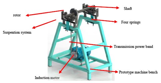
This section includes several elements, such as: technical requirements, description and machine design. It was also included the structure stress and modal analysis. Figure 9 denotes the overall overview of the designed and developed machine components.
Figure 9: Designed rotor balancing machine, drawing in Solidworks.
4.1 Technical Requirements
Based on the literature review. The single four run balanced plane method was selected for our research project. The 95% of the machine component can be balanced by the aforementioned method. The method requirements have to fulfill, the ratio of the rotor Length(L) and rotor diameter (D) had to be less than 5, and the rotation speed is not more than 1000 rpm.
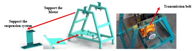
]]> 4.2 Prototype Machine BenchFigure 10 shows the designed machine bench, which has a variable vertical support that regulates the vertical position of the suspension system. Moreover, it was performed a theoretical structural analysis to determine, the structure resonances don’t coincide with the shaft, rotor and/or suspension system.
The bench is the structure in charge of supporting the suspension components, shaft and the rotor in the upper part. The lower part has a mechanism, a platform to support the induction motor. It also supports an induction motor of 1Hp of 20 Kg. This mechanism consists of tensioning the belt with the motor's own weight by means of a pendulum movement of the platform. It contains also an adjustable steel frame for vertical positioning of the suspension system.
Figure 10: Designed bench machine, drawing in Solidworks.
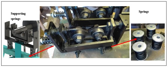
4.3 The Suspension System
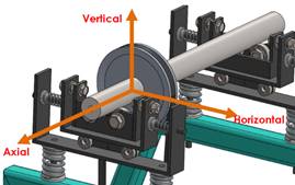
Figure 11 shows the suspension system. It can be seen the supporting shaft and rotor with three degrees of freedom: horizontal, vertical and pendulum in the axial direction. The characteristic of this system is that it can isolate or at least reduce the external vibrations phenomena.
Figure 11: Suspension prototype for rotor balancing measurement system.
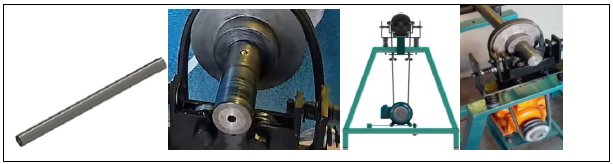
4.4 Shaft Designing System and Power Transmission
]]> Due to a large majority of industrial centrifugal fan rotors do not have their own shaft. It should be designed accurately as possible, see even Figure 12. The shaft designing can be seen in section 5, with the FEM and modal analysis. It was also included the power transmission based on ISO 1940-1.Figure 12: Shaft connected for balancing.
5. STRUCTURE STRESS AND MODAL ANALYSIS OF THE SYSTEM SHAFT, MACHINE BENCH, AND SUSPENSION SYSTEM
This section describes the formulation adopted for the numerical simulation of the shaft, machine bench, transmission power, and the suspension system. The developed rotor balancing system was also carried out on a theoretical modal analysis.
5.1 Shaft Structure Stress Analysis
The most common used shaft is the Ø38H6/K6 with 60 kg mass, which was selected for the project. H stands for tolerance value of the place to be assembled the shaft. Ø38 is the nominal shaft diameter, K is the shaft precision tolerance. In order to see it, if the selected shaft was appropriate for the characteristics of the project a structure stress analysis was applied, starting to calculate the external forces applying on the shaft, see Figure 13 for details.
Figure 13: The system initial reaction forces.
]]> The second Newton Law gives the following force equation:![]()
Where ![]() are the reaction forces in the supports A and B.
are the reaction forces in the supports A and B. ![]() is the rotor weight,
is the rotor weight, ![]() is shaft weight and
is shaft weight and ![]() is the pulley weight. The readers can see details in Table 1, the obtained results of the reactions forces, the results of the stress numerical analysis. Table 1 summaries the calculate forces and gives the references values to compare.
is the pulley weight. The readers can see details in Table 1, the obtained results of the reactions forces, the results of the stress numerical analysis. Table 1 summaries the calculate forces and gives the references values to compare.
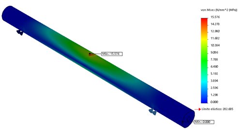
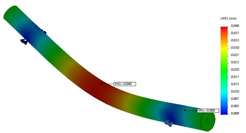
Figure 14 denotes the static stress analysis. Figure 14a) shows the maximum intensity in the central part with 15.57 Mpa, and the critical force is about 588 N. These values can be compared with the reference value of the AISI 1035 steel, showing that the shaft tension values will be in the region of the elastic part. The ![]() is 205 Mpa, giving the security ratio factor of 14. Figure 14b) illustrates a maximum displacement of 0.04 mm, due to the applied force of 588 N. It means the selected shaft will be operating in the safe region.
is 205 Mpa, giving the security ratio factor of 14. Figure 14b) illustrates a maximum displacement of 0.04 mm, due to the applied force of 588 N. It means the selected shaft will be operating in the safe region.
Figure 14: a) The shaft stress analysis and b) 3D model and finite element results for the shaft displacement.
The structural dynamic analysis can be seen in Figure 15. Figure 15a) illustrates the external torsional forces on the shaft, due to the transmission torque of the induction motor. It is coupled the shaft by a power transmission system. The initial weight condition was about 60 kg. The motor rotation frequency was 24 [Hz] (1400 [RPM]). The shaft natural frequency must be above the 24 Hz, in order to avoid resonances phenomena. In our case, see even Figure 15, the shaft natural resonances, according the results of the numerical analysis were above 455, 1582, and 2728 Hz, respectively. It indicates that the shaft will never resonate with the motor’s natural rotating frequency.
]]>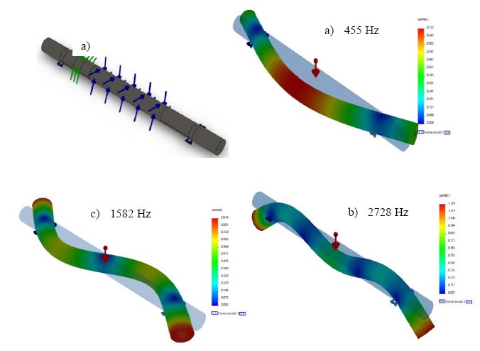
Figure 15: Modal analysis results.
Figure 16 shows the shaft’s resonance frequency around 455 Hz will have a structural stress of 29 M.pa which unlike the static is higher, but is still below the yield strength limit of the material. And it has a maximum displacement of 0.034 mm.
Figure 16: Von Misses stresses and displacement of the shaft first mode.
5.2 The System Suspension’s Stress Structure Analysis
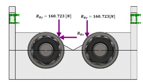
First, it was carried out the calculation of the reaction forces on the rolling bearings. Figure 17 shows a free body diagram with reactions forces and the displacement to be calculated due to the unbalances forces.
Figure 17: Free body diagram of the reactions forces.
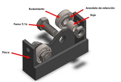
The main suspension system in Figure 18 is isolated from the suspension system with supporting springs. This is because, it has to support the object to measure and reduce the influence of external forces.
]]>Figure 18: a) Suspension main system, and b) Free body diagram with resulting forces.
The bearings reaction forces and the horizontal displacement of 2 mm were determined to assume to generate the unbalance force. The obtained calculated unbalance forces were RBx![]() , and
, and ![]() .
.
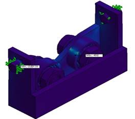
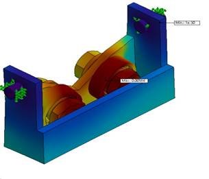
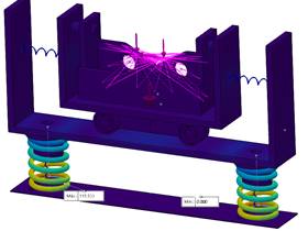
The second static Finite Element Method was carried out on the suspension system. It can be seen Figure 19; the maximum stress concentration is given in the bearing cage with a value of 50 Mpa. The stress value is below the yield limit of the bearing material of 620 MPa. The safety factor value is about 2. The maximum displacement occurs when the reference mass is mounted with a value of 0.00586 mm. It can also be stressed out that the main suspension system will not fail.
Figure 19: Main suspension system.
Taking into account the mass of unbalance, we have the force RBx = 40 N, causing a randomly vibration amplitudes, due to that force a displacement of 2 mm in the horizontal direction is obtained. As a result of that, any component will come into resonance with the axis.
Figure 20: A) Suspension system front view, b) Overall view of the suspension system.
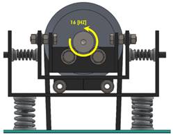
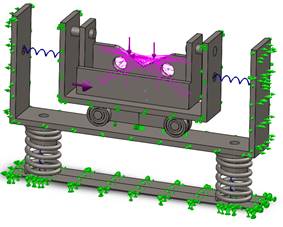
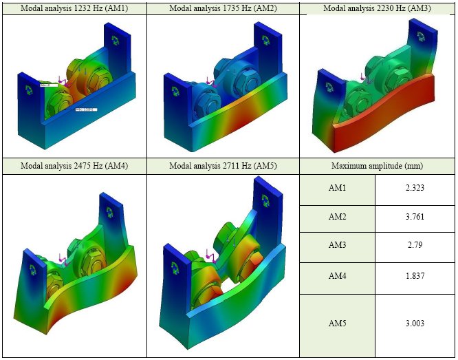
]]> The dynamical stress analysis was performed, as input speed with 16 Hz. Firstly, Figure 21 illustrates the stress analysis with the first five resonance modes: 1232, 1735, 2230, 2475 and 2711 Hz, respectively. It can also be stressed out that there is no risk for any resonance phenomena can happen between the rotating speed and the main suspension system.Finally, it was performed the entire suspension structure stress system analysis, see Figure 22 a) for details. The resonance obtained frequencies are 84, 97, 177, 287, and 290 Hz, respectively. Figure 22b) denotes the maximum stress value of 40 Mpa at frequency of 98 Hz, which is related to the second resonance of the system. The obtained value is lower of the reference value, which does not exceed the elastic limit of the material of 180 Mpa. The resonant frequencies are quite high, indicating that any resonance phenomena can happen in the developed suspension system.
To complete this entire section of suspension system analysis the following is concluded: All the analysis is for a rotor mass of critical conditions of 60 Kg, the suspension system will not fail when working at its operating frequency of 17 Hz. The rotating speed is lower than the structure resonance frequency. It is one requirement of the ISO 1940-1.
Figure 21: The first five resonance mode responses of the main suspension system.
Figure 22: a) Overall stress analysis of the suspension system and b) the highest stress tension in the structure.
5.3 Structure Machine Bench Stress Analysis
This section contains an extensive study of the structure bench stress analysis. Figure 23 shows the force applied in the structure with the analysis of the induction motor’s weight, rotor loads, shaft, suspension system and pulley. The sum gives a total weight of 665 N, this load is divided by four supporting points on the bench, in which there is a force of 166 N at each point, as it can be seen in Figure 23.
]]>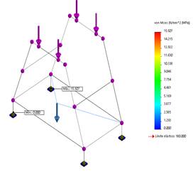
Figure 23: 3D numerical analysis of the machine bench structure.
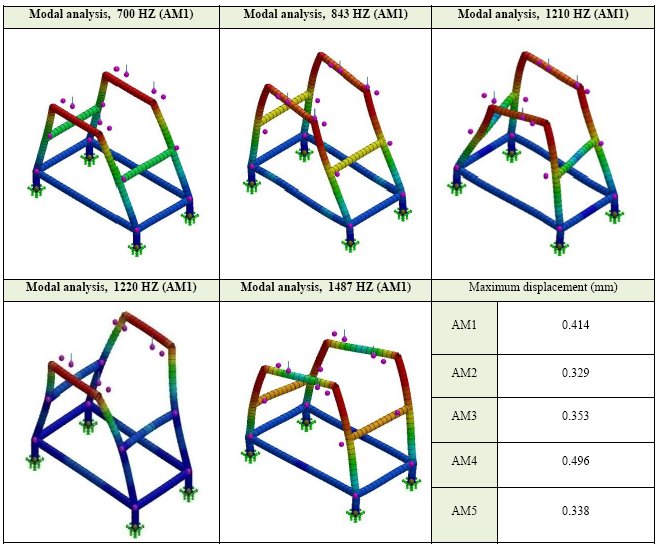
The obtained results of the numerical analysis shown, as maximum tension of 15.5 N/mm2. It gives a factor security of 130. In Figure 24 illustrates the results of the numerical modal analysis of the bench structure. It shows the first five representative results of the stress analysis. It was shown before, in a previous result in figure 15, that the natural frequency of the shaft was around 455 Hz and the first resonance in the machine bench is about 700 Hz. It means that we are above the shaft resonance frequency and the rotating shaft frequency about 17 Hz, which means that machine bench structure will not vibrate due the resonance phenomena of the shaft.
Figure 24: Summarize modal analysis results of the bench machine.
6. MEASUREMENT SET-UP AND ANALYSIS PROCEDURE
This section contains the measurement set-up and the analysis procedure for the developed measurement system. Figure 25 shows and overview of the structure bench, suspension system, induction motor, shaft, and a rotor(fan).
The applied method for the rotor balancing was the single plane balancing with four-runs method (25). The above method is used for machines that operates below the critical speed an L/D ratio than 0.5. L means the length of the rotor, and D is the rotor diameter. The rotating speed has to below 1000 rpm.
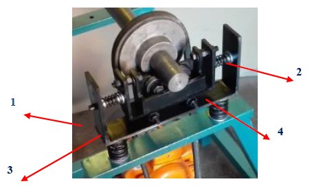
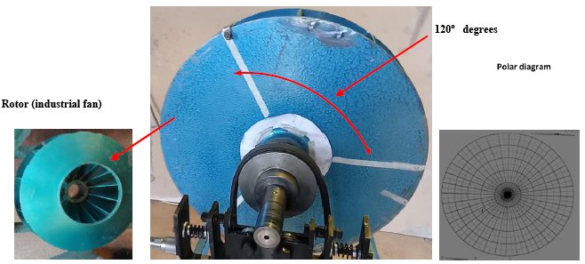
So, the four-runs method was used to balance the single plane rotor, using one vibration data channel. This method uses only the vibration signals to balance a rotor. There is no need for a tacho signal to measure rotor angle values. Figure 26 illustrates the suspension system with four vibration measurement points to calibrate the equipment, in order to obtain similar vibration amplitudes by adjusting the strength of the springs. Figure 27 denotes the three measurement points at 0 o, 120 o and 240o at the rotor, with the reference mass to start the rotor balancing process.
]]>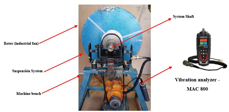
Figure 25: Overview of the structure bench, suspension system, induction motor, shaft, and a rotor (fan).
Figure 26: System suspension with the four vibration measurement points.
Figure 27: Three measurement points at 0 o, 120 o and 240o at the rotor.
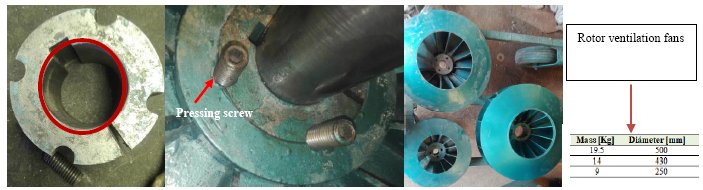
Figure 28 shows the rotor ventilation fans and the adjusting system with the pressing screw
]]> Figure 28: The rotor ventilation fans and the adjusting system with the pressing screw.
7. ANALYSIS AND RESULTS OF THE ROTOR BALANCING SYSTEM: A CASE STUDY
Initially, the rotor balancing equipment is carried out by a calibration procedure. That is, to measure at four points in horizontal positions, see the Figure 29. All tests must be calculated according to ISO 1940-1. Figure 29a) shows a diagram to facilitate the location of measurement points to collect data. The idea is to obtain similar vibration amplitude in all four measurement points; by adjusting the vertical springs stiffness until similar vibration values are obtained. Once the machine has been calibrated with the shaft, the rotor can start the balancing procedure.
Figure 29: Rotor balancing measurement points (1H, 2H, 3H, and 4H).
To perform the rotor balance analysis, it can be performed in the following procedure:
Figure 30: Flowchart for calculating the rotor balancing procedure.
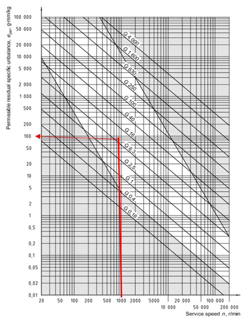
The input data was, ![]() . Initially, it has to be define the permissible residual specific unbalance (
. Initially, it has to be define the permissible residual specific unbalance (![]() ), which is the micron displacement of the main axis of inertia to the axis of rotation. This can be obtained from Figure 31, by applying the speed of 1000 rpm and the quality criterion of G6.3, which gives
), which is the micron displacement of the main axis of inertia to the axis of rotation. This can be obtained from Figure 31, by applying the speed of 1000 rpm and the quality criterion of G6.3, which gives ![]() . The permissible residual specific unbalance is
. The permissible residual specific unbalance is ![]() . The recommended degree of balancing quality for fan rotors is G6.3, this data determines the specific residual imbalance (specific unbalance quantity). The result obtained helps to find the permissible residual unbalance.
. The recommended degree of balancing quality for fan rotors is G6.3, this data determines the specific residual imbalance (specific unbalance quantity). The result obtained helps to find the permissible residual unbalance.
Figure 31: Diagram for detection of the permissible residual specific unbalance.
![]()
The Admissible Unbalance (AU), refers the amount of mass that may be causing unbalance in the rotor. The AU value indicates the unbalance mass somewhere in the rotor. Let initiates with the balancing of a rotor mass of M=19.5 kg. The Admissible Unbalance will be:
![]()
The permissible unbalance value ![]()
![]() gr
gr
The centrifugal force will be:
![]()
![]()
where g is the gravitational acceleration, 9.81 m/s2, M is the rotor mass and r the rotor radio, and k=2 is the factor recommended by “IRD Mech-analysis” [21]. The test mass will be ![]() .
.
The four-run rotor balancing single method has the following measurement procedure (ISO 1940-1):
]]> Figure 32: The polar plane defines the place and the direction of the mass in the rotor.a) Throughout the first run, the reference vibration signal is recorded in four vibration measurement points at 1H, 2H, 3H and 4H, see Figure 26 and 29. These vibration measurements are performed in order have almost the same vibration amplitudes. If it necessary, the suspension systems’ springs can be adjusted to get the right values.
b) Measured the vibration values with three locations (0o, 120o and 240o) on the rotor is attach the trial weight, respectively. It has to be drawn four circles in the polar plane, see even the drawn in Figure 32. It can be seen the r, r1, r2, r3 are the radios. The first circle is due to the reference signal; the radio is the amplitude times 2. The circles can be generated also with r1, r2, and r4.
c) To calculate the amount of mass and location in degrees, the correction mass can be determined by a polar diagram or mathematically by the software “Adash”. It has to be included in the analysis the weight value.
d) Finally, it was calculated the distance and the degree of the weight to be adjust, in order to reduce the unbalance of the system. Determine the point where the circles r, r1,r2 r3 are crossed and draw a vector Ep from the center until it cuts with the three circles. The vector indicates the angular position of the correction mass, see Figure 32.
The obtained values were with the first run 13.079 mm/s without test mass. At 120o degrees was placed the test mass at Vibration A and the obtained value was 8.735mm/s. Vibration B is 9.655, and Vibration C were 14.448 mm/s, respectively. After collecting the 4 vibration readings we proceed to calculate the correction mass and its direction.
After drawing the circles in the polar diagram, taking as a diameter twice the measured vibration amplitude, a line is placed in a middle region that form the four circles, as shown in Figure 32. Giving a value of 6.54 cm now the data is replaced in equation (9).
![]()
where ![]() is the correction mass,
is the correction mass, ![]() is velocity reference with 6.54 mm/s, and the mass
is velocity reference with 6.54 mm/s, and the mass ![]() gr, and IR=13.079 mm/s. The obtain value of mc=41.85 gr at 60o from A.
gr, and IR=13.079 mm/s. The obtain value of mc=41.85 gr at 60o from A.
According the ISO 1940-1, the residual unbalance ![]() , has to be higher than the permissible unbalance
, has to be higher than the permissible unbalance ![]() . Let`s control it.
. Let`s control it.

Where the ![]() is the calculated distance by the polar plane. As a result, the rotor is still unbalanced because
is the calculated distance by the polar plane. As a result, the rotor is still unbalanced because ![]() >
> ![]() for a rotor with the characteristics of the mass is 19.5 Kg and 500 mm rotor diameter. Both the correction mass and the location are correct, however, in order to reduce the
for a rotor with the characteristics of the mass is 19.5 Kg and 500 mm rotor diameter. Both the correction mass and the location are correct, however, in order to reduce the ![]() , the mass has to be moved a radius further from the axis, according ISO 1940-1. For ease when placing the correction mass in the rotor, take the maximum radius of R=250 mm.
, the mass has to be moved a radius further from the axis, according ISO 1940-1. For ease when placing the correction mass in the rotor, take the maximum radius of R=250 mm.
![]()
By replacing data with the correct mass and new position:
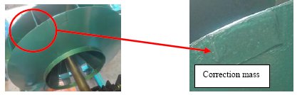
]]>The correction mass of 10.91 gr and 60o from position A was welded in the rotor. Figure 33 shows the correction mass in the rotor of 19.5 Kg.
Figure 33: Location of the correction mass and angle.
Table 2 shows the summery of the analysis results. It can be pointed out that the requirement was of G6.3, however the obtained results with the developed rotor balancing measurement system was about G2.6, see even Table 2.
To validate the obtained results of the developed rotor balancing system. The measured vibration signal was used as input data in a standard vibration measurement instrument, “MAC 200”. This generates a report to be observed how the vibration amplitudes decreases below the ISO 1940-1. In our case was the reference value G13 and it was obtained G2.8, see Table 2. In Figure 34 shows the obtained results from the standard analysis instrument, the first four vibration measurements have higher amplitudes, however. After the balancing procedure, it was obtained vibration reduction down to 2.6 mm/s, which means quality grade of G2.6 based on ISO 1940-1.
Figure 34: Rotor balancing report according the standard vibration analysis instrument, “MAC 800”.
]]> 8. DISCUSSIONS
Mass unbalance in a rotating system usually produces unwanted centrifugal forces that reduces the life span of mechanical elements. To minimize the harmful effects of unbalance, the rotor balancing is frequently considering to be upfront technique that is carried out in guidance with the instruction specified by the balancing machine manufacturer.
Before balancing procedure, there is some attention that should be addressed. The situation can appear looks like rotor unbalance; however, there are several cases that can appear similar case for example: Soft foot, cracked shaft, excessive bearing clearance, shaft misalignment, bent shaft. Therefore, the rule of thumb is to properly diagnose the cause of mechanical behavior before starting with the balancing procedure.
Finally, the cost of the developed rotor balancing system, comparing standard alternatives with the same accuracy and precision, was about 87% less in price.
9. CONCLUSIONS
There is a steadily growing demand for reliable, versatile measurement rotor balancing system which can be used to determine the machine parts unbalances. The effect of these causes are the increase of vibration amplitudes, causing damage to elements of the machines, mainly in the bearings, reduce useful life time, and increase fatigue failure in machines. The industry requires that machines have to operate continuously, efficient maintenance philosophy, and reduce the down time. Therefore, this research work has the main objective to design and develop a low-cost rotor balancing measurement system for industrial applications.
Based on the literature review was selected the four-run single plane method for the simplicity and it fulfills the requirements. The designing and prototype manufacturing was applied according ISO 1940-1.
For the designing, the structural stress analysis and the modal analysis was used The Solidworks software. It was carried out and extensive numerical analysis with FEM, of the developed measurement system, in order to identify the structure resonance frequencies to avoid with the induction motor rotation speed.
The cost of the developed rotor balancing system, comparing standard alternatives with the same precision requirements, was about 87% less in price.
]]> Finally, it was developed a rotor balancing measurement system. It showed the ability, and potential to use the developed equipment in industrial environment. Moreover, it has been shown that the vibration analysis measurements and the applied analysis method has worked accurate for unbalance detection and reduction of vibration levels from G6.2 to G2.8.
10. ACKNOWLEDGEMENT
The authors want to thank UPB for their financial support for the execution of this research project.
11. REFERENCES
[1] J. Taylor. Vibration-Analysis-Handbook-. Thomsson 2004, vol 2, ISBN-10: 0964051729, ISBN-13:978-0964051720. [ Links ]
[2] J. Thonson.Theory-of-Vibration-with-application-5th. McGraw-Hill. 2001.
[3] Fan Hongwei, Jing Minqing, y Liu Heng, Program design of an online dynamic balancing system for grinding-wheel and spindle, 2011 IEEE International Conference on Computer Science and Automation Engineering, Shanghai, China, 2011, pp. 173-177.
[4] JYOTIK~1. http://irdbalancing.com/assets/balance_quality_requirements_of_rigid_rotors.pdf PDF.
]]> [5] PhD Thesis On condition Based Maintenance.pdf.[6] Robert Bond Randall-Vibration-based Condition Monitoring_ Industrial, Automotive and Aerospace Applications-Wiley (2011).pdf.
[7] A. Prajapati, J. Bechtel, y S. Ganesan. Condition based maintenance: a survey, Journal of Quality in Maintenance Engineering, vol. 18, n.o 4, pp. 384-400, oct. 2012.
[8] S. K. Sweeney y K. J. Fisher. Reduction of Rotating Imbalance Measurement Variation Resulting From Test Apparatus Redesign, en Innovations in Engineering Education: Mechanical Engineering Education, Mechanical Engineering/Mechanical Engineering Technology Department Heads, Orlando, Florida, USA, 2005, vol. 2005, pp. 427-434.
[9] D.-J. Han, Generalized modal balancing for non-isotropic rotor systems, Mechanical Systems and Signal Processing, vol. 21, n.o 5, pp. 2137-2160, jul. 2007.
[10] A. Wang, X. Cheng, G. Meng, Y. Xia, L. Wo, y Z. Wang. Dynamic analysis and numerical experiments for balancing of the continuous single-disc and single-span rotor-bearing system, Mechanical Systems and Signal Processing, vol. 86, pp. 151-176, mar. 2017.
[11] H. Cao, D. He, S. Xi, y X. Chen. Vibration signal correction of unbalanced rotor due to angular speed fluctuation. Mechanical Systems and Signal Processing, vol. 107, pp. 202-220, jul. 2018.
[12] R. Ambur y S. Rinderknecht. Unbalance detection in rotor systems with active bearings using self-sensing piezoelectric actuators. Mechanical Systems and Signal Processing, vol. 102, pp. 72-86, mar. 2018.
[13] A. K. S. Jardine, D. Lin, y D. Banjevic. A review on machinery diagnostics and prognostics implementing condition-based maintenance. Mechanical Systems and Signal Processing, vol. 20, n.o 7, pp. 1483-1510, oct. 2006.
[14] S. Khan y T. Yairi. A review on the application of deep learning in system health management, Mechanical Systems and Signal Processing, vol. 107, pp. 241-265, jul. 2018.
]]> [15] Robert Bond Randall-Vibration-based Condition Monitoring_ Industrial, Automotive and Aerospace Applications-Wiley (2011).pdf.[16] J. Veldman, W. Klingenberg, y H. Wortmann. Managing condition‐based maintenance technology: A multiple case study in the process industry. Journal of Quality in Maintenance Engineering, vol. 17, n.o 1, pp. 40-62, mar. 2011.
[17] J. Baek. An intelligent condition‐based maintenance scheduling model. International Journal of Quality & Reliability Management, vol. 24, n.o 3, pp. 312-327, mar. 2007.
[18] William T. Thomson , Marie Dillon Dahleh, Theory of Vibration with Applications, 5th ed. Prentice Hall, 1998.
[19] Jason Tranter, Capacitación en Vibración Categoría I , Manual del Curso, Mobius Institute. [ Links ]
[20] Robert B Mcmillan, Rotating Machinery: Practical Solutions to Unbalance and Misalignment. The fairmont Press, INC, Libum, Geogia, 2004.
[21] IRD Mechanalysis, IRD Mechanalysis, Vibration Technology - 1, Student Workbook. Columbus, Ohio, 1988. [ Links ]
[22] Herbert Kruger C.A. Fuentes de Errores comunes Durante el Balanceo», Colombia.
[23] Richard G. Budynas y J. Keith Nisbett, Diseño en ingeniería mecánica de Shigley, Octava. McGraw-Hill.
[24] Bruel & Kjaer. Static and Dynamic Balancing of Rigid Rotors.
]]>[25] Jason Tranter, Capacitación en Vibración Categoría III , Manual del Curso, Mobius Institute. [ Links ]
]]>
 b)
b)