<?xml version="1.0" encoding="ISO-8859-1"?><article xmlns:mml="http://www.w3.org/1998/Math/MathML" xmlns:xlink="http://www.w3.org/1999/xlink" xmlns:xsi="http://www.w3.org/2001/XMLSchema-instance">
<front>
<journal-meta>
<journal-id>2518-4431</journal-id>
<journal-title><![CDATA[Investigación & Desarrollo]]></journal-title>
<abbrev-journal-title><![CDATA[Inv. y Des.]]></abbrev-journal-title>
<issn>2518-4431</issn>
<publisher>
<publisher-name><![CDATA[UNIVERSIDAD PRIVADA BOLIVIANA]]></publisher-name>
</publisher>
</journal-meta>
<article-meta>
<article-id>S2518-44312019000100002</article-id>
<title-group>
<article-title xml:lang="en"><![CDATA[SRESLi: SMART RENEWABLE ENERGY STREET LIGHTING SYSTEM]]></article-title>
<article-title xml:lang="es"><![CDATA[SRESLi: SISTEMA DE ILUMINACIÓN VIAL INTELIGENTE CON ENERGÍA RENOVABLE]]></article-title>
</title-group>
<contrib-group>
<contrib contrib-type="author">
<name>
<surname><![CDATA[Cañipa]]></surname>
<given-names><![CDATA[Fabiana]]></given-names>
</name>
<xref ref-type="aff" rid="A01"/>
</contrib>
<contrib contrib-type="author">
<name>
<surname><![CDATA[Arnez]]></surname>
<given-names><![CDATA[Fabio]]></given-names>
</name>
<xref ref-type="aff" rid="A03"/>
</contrib>
<contrib contrib-type="author">
<name>
<surname><![CDATA[Ormachea]]></surname>
<given-names><![CDATA[Omar]]></given-names>
</name>
<xref ref-type="aff" rid="A01"/>
</contrib>
<contrib contrib-type="author">
<name>
<surname><![CDATA[Rivero]]></surname>
<given-names><![CDATA[Armando]]></given-names>
</name>
<xref ref-type="aff" rid="A03"/>
</contrib>
<contrib contrib-type="author">
<name>
<surname><![CDATA[Dozio]]></surname>
<given-names><![CDATA[Gian Carlo]]></given-names>
</name>
<xref ref-type="aff" rid="A03"/>
</contrib>
<contrib contrib-type="author">
<name>
<surname><![CDATA[Escobar]]></surname>
<given-names><![CDATA[Erick]]></given-names>
</name>
<xref ref-type="aff" rid="A01"/>
</contrib>
</contrib-group>
<aff id="A01">
<institution><![CDATA[,Universidad Privada Boliviana Centro de Investigaciones Ópticas y Energías (CIOE) ]]></institution>
<addr-line><![CDATA[ ]]></addr-line>
</aff>
<aff id="A02">
<institution><![CDATA[,Universidad Privada Boliviana Centro de Investigaciones de Nuevas Tecnologías Informáticas (CINTI) ]]></institution>
<addr-line><![CDATA[ ]]></addr-line>
</aff>
<aff id="A03">
<institution><![CDATA[,Scuola Universitaria Professionale della Svizzera Italiana (SUPSI)  ]]></institution>
<addr-line><![CDATA[ ]]></addr-line>
</aff>
<pub-date pub-type="pub">
<day>00</day>
<month>00</month>
<year>2019</year>
</pub-date>
<pub-date pub-type="epub">
<day>00</day>
<month>00</month>
<year>2019</year>
</pub-date>
<volume>19</volume>
<numero>1</numero>
<fpage>5</fpage>
<lpage>23</lpage>
<copyright-statement/>
<copyright-year/>
<self-uri xlink:href="http://www.scielo.org.bo/scielo.php?script=sci_arttext&amp;pid=S2518-44312019000100002&amp;lng=en&amp;nrm=iso"></self-uri><self-uri xlink:href="http://www.scielo.org.bo/scielo.php?script=sci_abstract&amp;pid=S2518-44312019000100002&amp;lng=en&amp;nrm=iso"></self-uri><self-uri xlink:href="http://www.scielo.org.bo/scielo.php?script=sci_pdf&amp;pid=S2518-44312019000100002&amp;lng=en&amp;nrm=iso"></self-uri><abstract abstract-type="short" xml:lang="en"><p><![CDATA[Conventional street lighting systems do not allow controlling the light intensity depending on the traffic of pedestrians or vehicles, only operate in two automatic modes (on/off) according to the availability of daylight and consume enormous amounts of electric energy. In this article, we describe the design, development and implementation of a new intelligent street lighting system that is based on LED technology, an energy-efficient embedded wireless control device (hardware) designed from scratch, and photovoltaic solar energy. The embedded device includes specialized firmware and an energy-efficient wireless communication protocol, that allows to form a network of infrared sensors to detect pedestrians and vehicles, so as to control and dim the LED luminaires. We implemented a pilot system in a back road of the campus of Universidad Privada Boliviana, in the city of Cochabamba, Bolivia, where energy consumption measurements confirm energy savings of 72.8% thanks to the developed intelligent control system.]]></p></abstract>
<abstract abstract-type="short" xml:lang="es"><p><![CDATA[Los sistemas convencionales de iluminación vial no permiten el control de la intensidad de luz en función del tráfico de peatones o vehículos, sólo tienen dos modos de operación automático (prendido/apagado) dependiendo de la luz del día, y consumen una gran cantidad de energía eléctrica. En este artículo se describe el diseño, desarrollo, e implementación de un nuevo sistema de iluminación vial inteligente basado en tecnología LED, un dispositivo electrónico embebido inalámbrico (hardware) de bajo consumo energético desarrollado desde cero, y energía solar fotovoltaica. El dispositivo embebido incluye firmware especializado y un protocolo de comunicación inalámbrico energéticamente eficiente, que permite conformar una red de sensores infrarrojos de detección de peatones y vehículos, para el control y regulación de intensidad de las luminarias LED. Un piloto fue instalado en una calle aledaña al campus de la Universidad Privada Boliviana en la ciudad de Cochabamba, Bolivia, donde se realizaron medidas del consumo energético del sistema, que confirman un ahorro energético del 72.8% gracias al control inteligente desarrollado.]]></p></abstract>
<kwd-group>
<kwd lng="en"><![CDATA[Street Lighting System]]></kwd>
<kwd lng="en"><![CDATA[Photovoltaic System]]></kwd>
<kwd lng="en"><![CDATA[Intelligent Wireless Control System]]></kwd>
<kwd lng="en"><![CDATA[Energy Efficiency]]></kwd>
<kwd lng="es"><![CDATA[Sistema de Iluminación Vial]]></kwd>
<kwd lng="es"><![CDATA[Sistema Fotovoltaico]]></kwd>
<kwd lng="es"><![CDATA[Sistema de Control Inteligente Inalámbrico]]></kwd>
<kwd lng="es"><![CDATA[Eficiencia Energética]]></kwd>
</kwd-group>
</article-meta>
</front><body><![CDATA[ <p align="left"><font color="#800000" size="2" face="Verdana, Arial, Helvetica, sans-serif"><b>DOI:</b> 10.23881/idupbo.019.1-1i</font></p>     <p align="right"><font size="2"><b><font face="Verdana, Arial, Helvetica, sans-serif">ART&Iacute;CULOS &ndash; INGENIER&Iacute;AS</font></b></font></p>     <p>&nbsp;</p>     <p align=center><font size="4" face="Verdana, Arial, Helvetica, sans-serif"><b>SRESLi: SMART RENEWABLE ENERGY   STREET LIGHTING SYSTEM</b></font></p>     <p align=center>&nbsp;</p>     <p align=center><font size="3" face="Verdana, Arial, Helvetica, sans-serif"><b>SRESLi: SISTEMA DE ILUMINACI&Oacute;N   VIAL INTELIGENTE CON ENERG&Iacute;A RENOVABLE</b></font></p>     <p align=center>&nbsp;</p>     <p align=center>&nbsp;</p>     <p align=center><font size="2" face="Verdana, Arial, Helvetica, sans-serif"><b>Fabiana Ca&ntilde;ipa<sup>1</sup>, Fabio Arnez<sup>3</sup>, Omar Ormachea<sup>1</sup>, Alex Villaz&oacute;n<sup>2</sup>, Armando Rivero<sup>3</sup>, Gian Carlo Dozio<sup>3</sup> and Erick Escobar<sup>1</sup></b></font></p>     <p align=center><font size="2" face="Verdana, Arial, Helvetica, sans-serif"><sup>1</sup><i>Centro de Investigaciones &Oacute;pticas y   Energ&iacute;as </i>(CIOE)</font>    ]]></body>
<body><![CDATA[<br>   <font size="2" face="Verdana, Arial, Helvetica, sans-serif"><sup>2</sup><i>Centro de Investigaciones de Nuevas     Tecnolog&iacute;as Inform&aacute;ticas </i>(CINTI)<i><sup>&nbsp;</sup></i></font>    <br>   <font size="2" face="Verdana, Arial, Helvetica, sans-serif"><i>Universidad Privada     Boliviana&nbsp;</i></font>    <br>   <font size="2" face="Verdana, Arial, Helvetica, sans-serif"><a href="mailto:oormachea@upb.edu">oormachea@upb.edu</a></font>    <br>   <font size="2" face="Verdana, Arial, Helvetica, sans-serif"><sup>3</sup><i> Scuola Universitaria Professionale della     Svizzera Italiana </i>(SUPSI)</font></p>     <p align=center><font size="2" face="Verdana, Arial, Helvetica, sans-serif">(Recibido el 28 de mayo 2019,   aceptado para publicaci&oacute;n el 28 de junio 2019)&nbsp;</font></p>     <p>&nbsp;</p>     <p>&nbsp;</p> <hr noshade>     <p><font size="2" face="Verdana, Arial, Helvetica, sans-serif"><b>ABSTRACT</b></font></p>     <p align="justify"><font size="2" face="Verdana, Arial, Helvetica, sans-serif">Conventional   street lighting systems do not allow controlling the light intensity depending   on the traffic of pedestrians or vehicles, only operate in two automatic modes   (on/off) according to the availability of daylight and consume enormous amounts   of electric energy. In this article, we describe the design, development and   implementation of a new intelligent street lighting system that is based on LED   technology, an energy-efficient embedded wireless control device (hardware)   designed from scratch, and photovoltaic solar energy. The embedded device   includes specialized firmware and an energy-efficient wireless communication   protocol, that allows to form a network of infrared sensors to detect   pedestrians and vehicles, so as to control and dim the LED luminaires. We   implemented a pilot system in a back road of the campus of Universidad Privada   Boliviana, in the city of Cochabamba, Bolivia, where energy consumption   measurements confirm energy savings of 72.8% thanks to the developed   intelligent control system.&nbsp;</font></p>     <p align="justify"><font size="2" face="Verdana, Arial, Helvetica, sans-serif"><b>Keywords:</b> Street Lighting System,   Photovoltaic System, Intelligent Wireless Control System, Energy Efficiency.</font></p> <hr align="JUSTIFY" noshade>     ]]></body>
<body><![CDATA[<p align="justify"><font size="2" face="Verdana, Arial, Helvetica, sans-serif"><b>RESUMEN</b></font></p>     <p align="justify"><font size="2" face="Verdana, Arial, Helvetica, sans-serif">Los sistemas   convencionales de iluminaci&oacute;n vial no permiten el control de la intensidad de   luz en funci&oacute;n del tr&aacute;fico de peatones o veh&iacute;culos, s&oacute;lo tienen dos modos de   operaci&oacute;n autom&aacute;tico (prendido/apagado) dependiendo de la luz del d&iacute;a, y   consumen una gran cantidad de energ&iacute;a el&eacute;ctrica. En este art&iacute;culo se describe   el dise&ntilde;o, desarrollo, e implementaci&oacute;n de un nuevo sistema de iluminaci&oacute;n vial   inteligente basado en tecnolog&iacute;a LED, un dispositivo electr&oacute;nico embebido   inal&aacute;mbrico (hardware) de bajo consumo energ&eacute;tico desarrollado desde cero, y   energ&iacute;a solar fotovoltaica. El dispositivo embebido incluye firmware   especializado y un protocolo de comunicaci&oacute;n inal&aacute;mbrico energ&eacute;ticamente   eficiente, que permite conformar una red de sensores infrarrojos de detecci&oacute;n   de peatones y veh&iacute;culos, para el control y regulaci&oacute;n de intensidad de las   luminarias LED. Un piloto fue instalado en una calle aleda&ntilde;a al campus de la   Universidad Privada Boliviana en la ciudad de Cochabamba, Bolivia, donde se   realizaron medidas del consumo energ&eacute;tico del sistema, que confirman un ahorro   energ&eacute;tico del 72.8% gracias al control inteligente desarrollado.&nbsp;</font></p>     <p><font size="2" face="Verdana, Arial, Helvetica, sans-serif"><b>Palabras Clave</b>: Sistema de Iluminaci&oacute;n Vial, Sistema   Fotovoltaico, Sistema de Control Inteligente Inal&aacute;mbrico, Eficiencia Energ&eacute;tica.</font></p> <hr noshade>     <p>&nbsp;</p>     <p>&nbsp;</p>     <p align="justify"><font size="3" face="Verdana, Arial, Helvetica, sans-serif"><b>1.&nbsp;&nbsp;&nbsp;&nbsp; INTRODUCTION</b></font></p>     <p align="justify"><font size="2" face="Verdana, Arial, Helvetica, sans-serif">Street&nbsp;lighting   is essential for citizen and road safety. It can be used to increase urban security   by improving safety for drivers, riders, and pedestrians. Driving at night is   more dangerous than driving in any other moment of the day - only a quarter of   all travels by car drivers are made during the nighttime (between 7pm and 8am),   yet this period accounts for 40% of fatal and serious injuries. In this   context, also pedestrians and vulnerable road users suffer from decreased   visibility in the dark [1]. The studies in [2, 3] suggest that street lighting   deployment may prevent road accidents and fatalities and significantly reduce   crime. In this sense, another study [4] suggests that, when risk for citizens   are considered carefully, techniques for power consumption reduction in street   lighting (i.e. light dimming, light switch off) can be applied without   affecting pedestrian security.&nbsp;</font></p>     <p align="justify"><font size="2" face="Verdana, Arial, Helvetica, sans-serif">Street lighting currently has   two major flaws and drawbacks. On the one hand, it   represents an energy consumption problem, accounting for 19% of the global use   of energy and approximately 6% of greenhouse gas emissions [5]. This is mainly due to the inefficiency of conventional street lighting   systems, as they operate continuously throughout the night, regardless of the   presence of pedestrians or vehicles. On   the other hand, in Bolivia and other developing countries, street lighting   systems in some peripheral areas are either deficient or nonexistent, due to   the fact that electricity transmission and distribution systems do not cover   the entire territory [6].</font></p>     <p align="justify"><font size="2" face="Verdana, Arial, Helvetica, sans-serif">Reducing CO2 emissions and   achieving energy efficiency is a core factor for the transition towards a   resource-efficient economy and the smart sustainable growth the world is   seeking today. Street lighting is an important part to achieve this goal, where   the highest amount of energy consumption related to it, is caused by   inefficient legacy systems. Strong financial and technological drivers suggest   that billions of dollars around the globe could be saved in energy costs per   year by switching to light-emitting diode (LED) technology. LED lights provide   two major benefits: reduce power consumption and have longer service life,   which is three to five times longer than legacy lighting technologies [7]. This   increase in service lifetime is also reflected in an important reduction of   costs for maintenance. Moreover, this technology is far more flexible than   legacy systems, by enabling the application of smart or intelligent electronic   control to adjust LED dimming to reduce energy consumption [5].</font></p>     <p align="justify"><font size="2" face="Verdana, Arial, Helvetica, sans-serif">Therefore,   traditional street lighting systems must be re-designed with an   energy-efficiency scope on all the systems involved. Firstly, loads must be   optimized, replacing High Pressure Sodium (HPS) lamps, or similar technologies,   with LED. In this way, an efficient conversion of electric energy into light is   ensured. Secondly, using optimized loads, it makes sense to replace the source   of electrical energy with renewable and clean energy, such as photovoltaic (PV)   solar energy. The use of PV systems avoids using fossil resources, thus   minimizing the impact on greenhouse emissions. In addition, thanks to their   great portability, simple installation, long-service life and the high   availability of the solar resource, makes PV systems an effective option for   isolated electrification systems for street lighting in developing countries   with good solar radiation conditions [8], as is the case for   Bolivia [9]. Thirdly, reducing the energy waste from having the   street lighting at 100% of its power all the time, to an adaptive solution that   varies the light intensity according to vehicles and pedestrian traffic, to   achieve energy savings.</font></p>     ]]></body>
<body><![CDATA[<p align="justify"><font size="2" face="Verdana, Arial, Helvetica, sans-serif">In this   paper, we describe a new smart street lighting system based on renewable   energy, that follows the aforementioned aims. The contributions of this paper   include:</font></p> <ul>       <li><font size="2" face="Verdana, Arial, Helvetica, sans-serif" align="justify">the design,     pilot implementation and testing of an energy-efficient street lighting system     (Smart Renewable Energy Street Lighting - SRESLi), which allows to     intelligently adapt light intensities according to the traffic of pedestrians     and vehicles;&nbsp;</font></li>       <li><font size="2" face="Verdana, Arial, Helvetica, sans-serif" align="justify"> the design     and implementation of specialized hardware, an embedded control device - the     SRESLi System Unit - which features a proprietary energy-efficient wireless     communication protocol;</font></li>       <li><font size="2" face="Verdana, Arial, Helvetica, sans-serif" align="justify"> the     optimization of energy consumption through a PV solar system for providing     electric power to the SRESLi System Units and LED lamps to obtain expected     lighting conditions; and&nbsp;</font></li>       <li><font size="2" face="Verdana, Arial, Helvetica, sans-serif" align="justify"> achieving     energy efficiency while taking care of citizen and road safety, thus finding the adequate balance     between energy consumption reduction (i.e. light dimming) and pedestrian     security to guarantee road safety.</font></li>     </ul>     <p align="justify"><font size="2" face="Verdana, Arial, Helvetica, sans-serif">The rest of this article is   structured as follows: Section 2 states the related work. Section 3 describes   the complete design and development of the SRESLi and the PV system. Section 4   includes the experimental setup, deployment of the pilot system, and   measurements of lighting levels and power consumption with and without SRESLi.   Section 5 concludes the article.</font></p>     <p align="justify">&nbsp;</p>     <p align="justify"><font size="3" face="Verdana, Arial, Helvetica, sans-serif"><b>2.&nbsp;&nbsp;&nbsp;&nbsp; RELATED WORK</b></font></p>     <p align="justify"><font size="2" face="Verdana, Arial, Helvetica, sans-serif">In current smart street   lighting systems, we can distinguish six key components: Communications,   sensors, processing power, dimming system, system-fault monitoring and power   consumption. In terms of communications for smart light control, two main   approaches exist: wired communications with Power Line Communications (PLC) and   wireless sensor networks (WSN) like the ZigBee stack [5, 10]. In general, the   preferred choice is WSN, due to major drawbacks from wired technologies   regarding heavy deployment, installation costs and maintenance. Furthermore,   the wireless alternative offers low-cost, easy installation, and scalability   [5]. Another type of wireless communications technology, GSM, is often used in   centralized street lighting systems mainly to report failures [11-13].</font></p>     ]]></body>
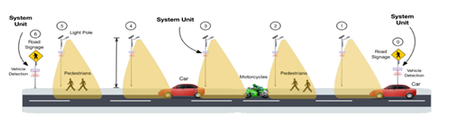
<body><![CDATA[<p align="justify"><font size="2" face="Verdana, Arial, Helvetica, sans-serif">Regarding light dimming systems,   three common techniques stand out for street lighting: The first one consists   of an optimized on/off switch driven by the detection of an object of interest,   e.g., using image processing [11]. The second approach consists in dimming on   demand through Pulse Width Modulation (PWM) brightness control [13]. Finally,   the last approach introduces the next level of 'intelligence' by implementing   adaptive traffic control based on probability models acquired by observation of   traffic volume on a specific road [5]. All the aforementioned approaches use   solar energy with PV systems independent from the conventional electric grid.   In [14], a street lighting system is proposed, by combining both PV and grid   energy systems, achieving positive yearly energy balance an intelligent control   system thanks to the use of infrared motion sensors measuring the speed and the   direction of the motion in the proximity of the luminaire. Smart controllers,   in turn, classify these motion signals as vehicle traffic, pedestrian traffic,   or no traffic, and adjust their dimming levels to the detected scenario.&nbsp;</font></p>     <p align="justify"><font size="2" face="Verdana, Arial, Helvetica, sans-serif">Existing approaches for   intelligent control systems, are based on off-the-shelf electronics for signal   processing (e.g., RaspberryPi, Arduino, ATmega16,   AT89S52), sensor hardware and communication modules (e.g., Zigbee, GSM,   Wifi, Bluetooth). Even though some of the processing units and communication   modules are designed for low-power consumption, they may require the   development of customized protocols to avoid, e.g., constant signal sensing, which   prevents optimizing the power consumption of the electronic control system   itself. This is for example, the case of Zigbee technology, for which current   communication protocols support beacon and non-beacon enabled networks. In   non-beacon-enabled networks, an unslotted CSMA/CA<a href="#_ftn1" name="_ftnref1" title="">[1]</a> channel   access mechanism is used, having their receivers continuously active, and   therefore requiring more power supply. In beacon-enabled network, normally   sleeping network slave nodes wake up periodically to receive a synchronizing   &quot;beacon&quot; from the network's control node. But listening for a beacon   wastes power too, particularly because timing uncertainties force nodes to turn   on early to avoid missing a beacon. One alternative is therefore to use TDMA<a href="#_ftn2" name="_ftnref2" title="">[2]</a>-based protocol   (based on IEEE 802.15.4 on the MAC layer of Zigbee) and design an   energy-efficient custom hardware for both processing and communication. This is   the approach followed for SRESLi for energy efficiency.</font></p>     <p align="justify">&nbsp;</p>     <p align="justify"><font size="3" face="Verdana, Arial, Helvetica, sans-serif"><b>3.&nbsp;&nbsp;&nbsp;&nbsp; DESIGN AND IMPLEMENTATION OF   SRESLI</b></font></p>     <p align="justify"><font size="2" face="Verdana, Arial, Helvetica, sans-serif">The SRESLi   system prioritizes and controls light dimming according to pedestrian and   vehicle traffic, thus, controlling energy consumption and promoting energy   savings when compared with traditional street lighting. The system was designed   to achieve maximum energy efficiency through a combination of wireless embedded   electronic control, LED technology and photovoltaic energy.</font></p>     <p align="justify"><font size="2" face="Verdana, Arial, Helvetica, sans-serif">The proposed system can detect   road users (i.e., pedestrians or vehicles) inside the operating environment and   adjust the streetlight illumination according to their flow. When some user is   detected within the operating environment, the illumination decision is   communicated to neighbor SRESLi-enabled light-poles near to the identified   users. Additionally, the SRELSLi System Units can enter different operation   modes to save energy and be functional only when is needed.&nbsp; <a href="#f1">Figure 1</a> shows the system environment and actors.&nbsp;</font></p>     <p align=center><font size="2" face="Verdana, Arial, Helvetica, sans-serif"><b><a name="f1"></a></b><img border=0 width=506 height=152 id="Imagen 42" src="/img/revistas/riyd/v19n1/a02_image001.png" alt="https://lh6.googleusercontent.com/yEGv8Q1am0qjb_h_rrwq-fAEMSdB3Sfzp8lz6g9vfmOnbePjv1B1jCR8AZFKTHKaQVQOXIXXe44LrpQi4J5NjcvA41PLpbVwH0a5-DuhfOS9RGBDJdfIOyv4EDK3gQ"></font></p>     <p align=center><font size="2" face="Verdana, Arial, Helvetica, sans-serif"><b>Figure 1</b>: SRESLi system environment and   actors.</font></p>     <p align="justify"><font size="2" face="Verdana, Arial, Helvetica, sans-serif">The SRESLi system can be   divided into three subsystems: the wireless embedded electronic control system,   the LED street lighting system, and the photovoltaic system, that are described   in the following subsections.</font></p>     <p align="justify"><font size="2" face="Verdana, Arial, Helvetica, sans-serif"><b>3.1 WIRELESS EMBEDDED   ELECTRONIC CONTROL - THE SRELSI SYSTEM UNIT</b></font></p>     ]]></body>
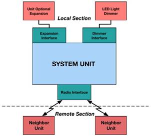
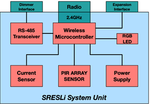
<body><![CDATA[<p align="justify"><font size="2" face="Verdana, Arial, Helvetica, sans-serif">The wireless embedded   electronic control subsystem of SRESLi (called in the following the &ldquo;SRESLi   System Unit&rdquo;), is a custom hardware device that we designed and developed from   scratch for energy efficient street-lighting control. The SRESLi System Unit   also features a proprietary communication protocol and a firmware to reduce the   power consumption and to avoid a centralized decision system.&nbsp;</font></p>     <p align="justify"><font size="2" face="Verdana, Arial, Helvetica, sans-serif"><b>Hardware Design</b></font></p>     <p align="justify"><font size="2" face="Verdana, Arial, Helvetica, sans-serif">The hardware design of the   SRESLi System Unit includes the unit hardware interface, the unit hardware   blocks and the printed circuit board (PCB) that are described in the following:</font></p>     <p><font size="2" face="Verdana, Arial, Helvetica, sans-serif" align="justify"><i>&#9642; Unit Hardware Interfaces</i></font></p>     <p align="justify"><font size="2" face="Verdana, Arial, Helvetica, sans-serif">Every SRESLi System Unit is   composed of three main hardware interfaces that allow communicating with other   units:</font></p> <ul>       <li><font size="2" face="Verdana, Arial, Helvetica, sans-serif" align="justify"><b>Radio     Interface:</b> This hardware interface is the 2.4GHz radio which is compliant with IEEE     802.15.4 specification [15]. This interface represents the physical layer of     our developed communication protocol.</font></li>       <li><font size="2" face="Verdana, Arial, Helvetica, sans-serif" align="justify"><b>Light Dimmer Interface:</b> allows the SRESLi System Units     to communicate with the LED light dimmer (located in the same light pole) to     send commands for turning on or off the LED light and control the light     intensity. This     interface uses a serial communication with RS-485 standard [16, 17].</font></li>       <li><font size="2" face="Verdana, Arial, Helvetica, sans-serif" align="justify"><b>Expansion     Interface:</b> allows to extend the hardware functionality of the SRESLi System Unit. This     interface is able to be configured programmatically to communicate to the     additional hardware expansion modules or to provide enhanced functionality,     e.g., connecting additional sensors, actuators, other types of communication     modules.</font></li>     </ul>     <p align="justify"><font size="2" face="Verdana, Arial, Helvetica, sans-serif"><a href="#f2">Figure 2</a> shows the SRESLi   System Unit hardware interfaces that communicate with other functional units of   the system, either locally or remotely.</font></p>     ]]></body>
<body><![CDATA[<p align=center><font size="2" face="Verdana, Arial, Helvetica, sans-serif"><b><a name="f2"></a></b><img border=0 width=302 height=273 id="Imagen 41" src="/img/revistas/riyd/v19n1/a02_image002.jpg" alt="https://lh4.googleusercontent.com/N47PeXwYdtQQdEEtGcnjHqBbTosHEKqwbDKtVL2tiji5ogmE-NrznU2oTj56aX3BbdsoVfDwe9i9OV_RlvsibDDt6VqvQI4js2OFnnhDptdTQDGXz7P6IjxIl8G4Yg"></font></p>     <p align=center><font size="2" face="Verdana, Arial, Helvetica, sans-serif"><b>Figure 2</b>: The SRESLi System Unit hardware interfaces.</font></p>     <p align=justify>&nbsp;</p>     <p align="justify"><font size="2" face="Verdana, Arial, Helvetica, sans-serif">&#9642;&nbsp; <i>Unit Hardware Blocks</i></font></p>     <p align="justify"><font size="2" face="Verdana, Arial, Helvetica, sans-serif">To satisfy the technical specifications, 5 blocks were   defined in the hardware design:</font></p> <ul>       <li><font size="2" face="Verdana, Arial, Helvetica, sans-serif" align="justify"><b>Wireless     Microcontroller:</b> Main processing unit of the device that includes a 2.4GHz radio transceiver     compliant with the IEEE 802.15.4 specification.</font></li>       <li><font size="2" face="Verdana, Arial, Helvetica, sans-serif" align="justify"><b>Current     sensor:</b> Measures the current flow and its direction. This block is used to measure the     power supply provided by the solar panels during the day (current flow from the     solar panel to the energy storage and the system), or by the energy storage     during the night.</font></li>       <li><font size="2" face="Verdana, Arial, Helvetica, sans-serif" align="justify"><b>PIR     array sensor:</b> Passive Infrared (PIR) sensor that detects the presence of pedestrians and     vehicles inside the system boundary.</font></li>       <li><font size="2" face="Verdana, Arial, Helvetica, sans-serif" align="justify"><b>RS-485     Transceiver:</b> Allows the communication of the systems units to their corresponding LED dimmer     to control the light intensity of the luminaire.</font></li>       <li><font size="2" face="Verdana, Arial, Helvetica, sans-serif" align="justify"><b>DC-DC     Regulator Power supply:</b> Provides a fixed operating voltage for the unit by regulating the     voltage input.</font></li>       ]]></body>
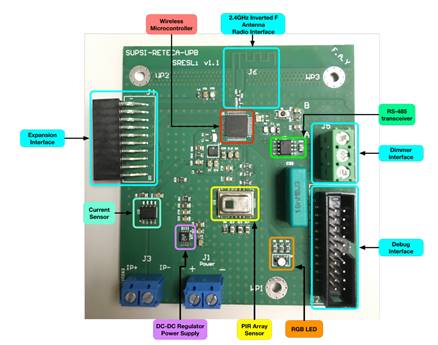
<body><![CDATA[<li><font size="2" face="Verdana, Arial, Helvetica, sans-serif" align="justify"><b>RGB LED:</b> Used for debugging purposes     and feedback signaling.</font></li>     </ul>     <p align="justify"><font size="2" face="Verdana, Arial, Helvetica, sans-serif"><a href="#f3">Figure 3</a> shows the hardware   block diagram of the SRESLi System Unit and the corresponding hardware   interfaces.</font></p>     <p align="center"><font size="2" face="Verdana, Arial, Helvetica, sans-serif"><a name="f3"></a><img border=0 width=297 height=206 id="Imagen 40" src="/img/revistas/riyd/v19n1/a02_image003.png" alt="https://lh5.googleusercontent.com/-TGSiKFXrXnBLKcOBPPyBgugvHF0u6KIfphqn9rzxuFYL1ZaPbAqoEqTCcxvjcfTYW6NtJNA18GypGtOWIJe436OTUql-p2qXpU9ahcXCKvFql5qIPtHrvb-gHT7XQ"></font></p>     <p align=center><font size="2" face="Verdana, Arial, Helvetica, sans-serif"><b>Figure 3</b>: SRESLi hardware block diagram.</font></p>     <p align="justify"><font size="2" face="Verdana, Arial, Helvetica, sans-serif">&#9642;&nbsp; <i>SRESLi System Unit PCB</i></font></p>     <p align="justify"><font size="2" face="Verdana, Arial, Helvetica, sans-serif">The SRESLi System Unit consists   of a two-layer PCB design for RF communication (2.4GHz). <a href="#f4">Figure 4</a> shows the   SRESLi System Unit PCB with all the hardware blocks and interfaces mounted on   the PCB board. All hardware components, connectors and most traces are located   in the top layer. SRESLi System Unit PCB design followed all the   recommendations from the microcontroller manufacturer described in [18].   However, the prototype design was implemented into a two-layer PCB in order to   reduce manufacturing costs. Even though RF design recommendations suggest   working on four layers PCBs, SRESLi System Unit&rsquo;s performance was not affected   during hardware validation tests for communication. <a href="#f4">Figure 4</a> shows the SRESLi   System Unit finished prototype after PCB manufacturing and electronic component   assembly processes. In addition, <a href="#f4">Figure 4</a> presents the locations and   descriptions of the most important components, connectors, and interfaces.</font></p>     <p align=center><font size="2" face="Verdana, Arial, Helvetica, sans-serif"><a name="f4"></a><img border=0 width=438 height=345 id="Imagen 39" src="/img/revistas/riyd/v19n1/a02_image004.jpg" alt="https://lh4.googleusercontent.com/cvTdMTi6cLv4h2--gSVl7fz5MgBoKHrLElBNr5-HHzEqhJn9HKoQiyGUYzwTWPAhuHtxw8M0NPkrQoCtOhTQ_dK_jksZtK4NxdGJirCxt_iPuprfNrdmhLGNK3sm0GJ3ax6PW-o"></font></p>     <p align=center><font size="2" face="Verdana, Arial, Helvetica, sans-serif"><b>Figure 4</b>: The SRESLi System Unit PCB Description.</font></p>     <p align=justify>&nbsp;</p>     ]]></body>
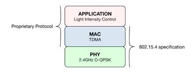
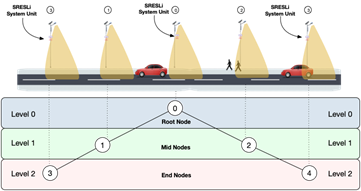
<body><![CDATA[<p align="justify"><font size="2" face="Verdana, Arial, Helvetica, sans-serif"><b>Communication Protocol</b></font></p>     <p align="justify"><font size="2" face="Verdana, Arial, Helvetica, sans-serif">As mentioned before, a smart   street lighting system requires communication between its units to control the   light intensity of LED lamps. For this reason, we developed a communication   protocol allowing the transmission and reception of light control commands. In   addition to the light control application, the protocol provides an energy   efficient access to the medium by using a TDMA approach. <a href="#f5">Figure 5</a> shows the   network layers where the protocol was developed. Also, is possible to see that   IEEE 802.15.4 specification is defined at Physical and Data-Link Layers. For   this purpose, the wireless microcontroller provides all the specification   functionality in its integrated transceiver. In this way, the chosen wireless   microcontroller uses the following default configuration for the specification:   O-QPSK<a href="#_ftn3" name="_ftnref3" title="">[3]</a> modulation at 2.4 GHz at the Physical layer and CSMA/CA channel access   mechanism at Data-Link layer. In our communication protocol, we changed the way   of accessing the channel to TDMA. In this way, energy efficiency is improved by   solving the need to continuously sense the communication channel by the CSMA/CA   approach. In consequence, the SRESLi protocol is mainly built upon the physical   layer of IEEE 802.15.4 specification.</font></p>     <p align=center><font size="2" face="Verdana, Arial, Helvetica, sans-serif"><a name="f5"></a><img border=0 width=396 height=149 id="Imagen 38" src="/img/revistas/riyd/v19n1/a02_image005.jpg" alt="https://lh5.googleusercontent.com/YZJhuuq8K9Di-J5lBoSClztg4BuNV4CGzSPm5TeTZJ0TGTJkqiCiHsFyv5RN0juMafec0U_nzwkEec4_AeIWXdnF5eLtww-mRe18VF-lx7vYI3yIxWFwqZODX02nc4gJxK4A4Ws"></font></p>     <p align=center><font size="2" face="Verdana, Arial, Helvetica, sans-serif"><b>Figure 5</b>: Network layers of SRESLi communication protocol.</font></p>     <p align=justify>&nbsp;</p>     <p align="justify"><font size="2" face="Verdana, Arial, Helvetica, sans-serif">&#9642;&nbsp; <b><i>Communication Architecture</i></b></font></p>     <p align="justify"><font size="2" face="Verdana, Arial, Helvetica, sans-serif">One of the major challenges in   TDMA communication approach is the timing control, because each node in a   Wireless Sensor Network (WSN) has an inaccurate hardware clock reference   (crystal oscillator). In the case of TDMA, clock offset and clock drift from   each network node has to be compensated in order to have a precise common   timescale over the network.</font></p>     <p align="justify"><font size="2" face="Verdana, Arial, Helvetica, sans-serif"><a href="#f6">Figure 6</a> shows the   communication architecture of the SRESLi network. In the figure, is possible to   distinguish five SRESLi System Units deployed in each light pole along a   street. The network follows a simple tree topology and according to the   physical position on the street, every unit has a specific address (physical   address) and a specific role in the network. The role of each node in the   network is fundamental at synchronization phase for the TDMA approach that   governs the medium access. Three types of nodes are presented according to   their functionality during the synchronization phase:</font></p> <ul>       <li><font size="2" face="Verdana, Arial, Helvetica, sans-serif" align="justify"><b>Level 0     - Root Node:</b> Unique type of node in the network, is the most important since provides the     clock reference for the other communication nodes .     There is only one root node in the entire network that provides a clock     reference for the other nodes.</font></li>       <li><font size="2" face="Verdana, Arial, Helvetica, sans-serif" align="justify"><b>Level 1     - Mid Nodes</b>:     This type of node is located between the root node and the end nodes. Mid nodes     receive a clock reference from their parent (root node) and also provide a     clock reference for their potential children (end nodes).</font></li>       ]]></body>
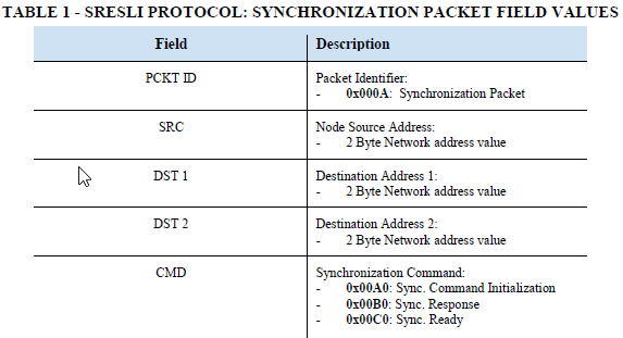
<body><![CDATA[<li><font size="2" face="Verdana, Arial, Helvetica, sans-serif" align="justify"><b>Level 2     - End Nodes:</b> Located physically at the edges (beginning or end) of the street that is being     covered. This type of node only receives a clock reference from their parents     (mid nodes).</font></li>     </ul>     <p align="justify"><font size="2" face="Verdana, Arial, Helvetica, sans-serif">Once the network nodes are   synchronized, the data transmission begins. The data transmitted and received   between the nodes carry the events occurred at each light pole. Later, the   light control application from each SRESLi System Unit process and identifies   events in the received data in order to control the LED light dimmer.&nbsp;</font></p>     <p align=center><font size="2" face="Verdana, Arial, Helvetica, sans-serif"><a name="f6"></a><img border=0 width=361 height=191 id="Imagen 37" src="/img/revistas/riyd/v19n1/a02_image006.png" alt="https://lh5.googleusercontent.com/yPidIPi91TT154uaYmJjxgX6Qalz3TJJGhnTwB6hq6utkfQ3C57d5jWI80C2j0C2le1YkD6i16FWEP-2rYWDFzBz_Njn8WWf7X0iSXsl9VSXZqk_dUD7OtcXNow13A"></font></p>     <p align="center"><font size="2" face="Verdana, Arial, Helvetica, sans-serif"><b>Figure   6</b>: SRESLi   Communication Architecture.</font></p>     <p align="justify"><font size="2" face="Verdana, Arial, Helvetica, sans-serif">&#9642;&nbsp; <b><i>Protocol Packet Structure</i></b></font></p>     <p align="justify"><font size="2" face="Verdana, Arial, Helvetica, sans-serif">SRESLi communication protocol   consists of two major stages in TDMA mode: Synchronization and Data   transmission. Each stage demands a specific data packet; those packets are   described in <a href="#f7">Figure 7</a>.</font></p>     <p align=center><font size="2" face="Verdana, Arial, Helvetica, sans-serif"><a name="f7"></a><img border=0 width=448 height=77 id="Imagen 36" src="/img/revistas/riyd/v19n1/a02_image007.jpg" alt="https://lh3.googleusercontent.com/mx8VUi_Y_mhvj7SqgZgtt4MJe5scrVXd52bD2MCaBSPElt1urYzqROkDwuP0mc4vAEJlsEyz-190mQwGzdbAaVE8jezaJZOhbbiYw46RlDCt8chI81SlVpdqykrPtQ"></font></p>     <p align=center><font size="2" face="Verdana, Arial, Helvetica, sans-serif"><b>Figure 7</b>: SRESLi Protocol:   Synchronization Packet Structure.</font></p> <ul>       <li><font size="2" face="Verdana, Arial, Helvetica, sans-serif" align="justify"><b>Synchronization     Packet: </b>Synchronization     packet has a fixed length of 10 Bytes, composed by five fields: Packet ID (PCKT     ID), Source, (SRC), Destination 1 (DST 1), Destination 2 (DST 2) and Command     (CMD). Each field has a size of 2 Bytes. <a href="#f7">Figure 7</a> shows the packet structure of     the Synchronization Packet and <a href="#t1">Table 1</a> describes each field and its values.</font></li>       ]]></body>
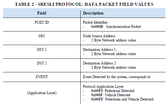
<body><![CDATA[<li><font size="2" face="Verdana, Arial, Helvetica, sans-serif" align="justify"><b>Data Packet: </b>As in the previous case, Data     packet has a fixed length of 10 Bytes, composed by five fields: Packet ID (PCKT     ID), Source, (SRC), Destination 1 (DST 1), Destination 2 (DST 2) and Event     (EVENT). Each field has a size of 2 Bytes. <a href="#f8">Figure 8</a> shows the packet structure     of the Data Packet. and <a href="#t2">Table 2</a> describes each field and its values. The     application layer field includes the three types of events that need to be sent     to the neighbor nodes for light control when pedestrians, vehicles or both are     detected.</font></li>     </ul>     <p align="center"><a name="t1"></a><img src="/img/revistas/riyd/v19n1/a02_table_01.png" width="573" height="311"></p>     <p align=justify><font size="2" face="Verdana, Arial, Helvetica, sans-serif"><b>&nbsp;</b></font></p>     <p align=center><font size="2" face="Verdana, Arial, Helvetica, sans-serif"><a name="f8"></a><img border=0 width=475 height=81 id="Imagen 35" src="/img/revistas/riyd/v19n1/a02_image008.jpg" alt="https://lh6.googleusercontent.com/WlLV4mZwqceWIl043HfKm-gFtRw3Oj50XNhzxnts26JmNnT1aWvuuGHhqxwSfX3hMYbKwPZZFXwlIRA-FhMs-krb9FlPgrjTjPo3t3NnPDPrypFkC7Bf8sac3gpKLA"></font></p>     <p align=center><font size="2" face="Verdana, Arial, Helvetica, sans-serif"><b>Figure 8</b>: SRESLi Protocol: Data Packet   Structure.</font></p>     <p align="justify">&nbsp;</p>     <p align=center><a name="t2"></a><img src="/img/revistas/riyd/v19n1/a02_table_02.png" width="551" height="347"></p>     <p align="justify"><font size="2" face="Verdana, Arial, Helvetica, sans-serif">&#9642;&nbsp; <b><i>MAC Layer: TDMA Channel Access   Approach</i></b></font></p> <ul>       <li><font size="2" face="Verdana, Arial, Helvetica, sans-serif" align="justify"><b><i>Synchronization: </i></b>Time synchronization follows a     simple flood mechanism, starts at the root node in level 0, continues through     level 1 with the mid nodes and then finishes in level three with the end nodes.     If the sequence fails at any level, the procedure is started again in the next     synchronization period by waiting again for a synchronization command (Sync. CMD) from the parent node at a     higher level.</font></li>       ]]></body>
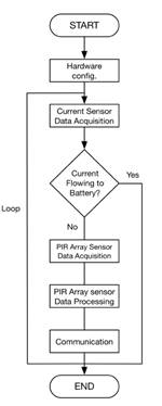
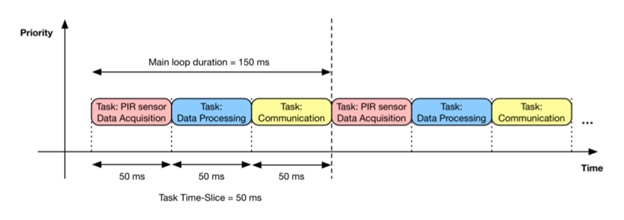
<body><![CDATA[<li><font size="2" face="Verdana, Arial, Helvetica, sans-serif" align="justify"><b><i>Data     Transmission and Reception</i></b>: Data transmission and reception starts after successful     node synchronization. Each node has specific transmission and reception time     window intervals.</font></li>     </ul>     <p align="justify"><font size="2" face="Verdana, Arial, Helvetica, sans-serif"><b>Firmware Design</b></font></p>     <p align="justify"><font size="2" face="Verdana, Arial, Helvetica, sans-serif">Embedded firmware stores   specialized software running in embedded device to control its functions and   also to interconnect with additional equipment. SRESLi system units include   firmware to execute the main application and to control light intensity.</font></p>     <p align="justify"><font size="2" face="Verdana, Arial, Helvetica, sans-serif">&#9642;&nbsp; <b><i>Main Firmware Application</i></b></font></p>     <p align="justify"><font size="2" face="Verdana, Arial, Helvetica, sans-serif">The main firmware is composed   of four tasks: Hardware configuration, sensor data acquisition (data   acquisition from current sensor and PIR array sensor), sensor data processing   and communication. <a href="#f9">Figure     9</a> shows the main application tasks in a flowchart.</font></p>     <p align=center><font size="2" face="Verdana, Arial, Helvetica, sans-serif"><a name="f9"></a><img border=0 width=150 height=374 id="Imagen 34" src="/img/revistas/riyd/v19n1/a02_image009.jpg" alt="https://lh6.googleusercontent.com/k8Aadivh9UGWQy1U8soeKfI81xu5pXnyWVqa4swNXfRYlBHEQG_gOu6TsXA2ubIB-5cN7zuTocvtqe4ZogekBxfM0jEeSAd0m0-xfu0FlqFzQPXZLekJVm1nv-04gsfqm7s40dI"></font></p>     <p align=center><font size="2" face="Verdana, Arial, Helvetica, sans-serif"><b>Figure 9</b>: SRESLi&rsquo;s firmware application   flowchart.</font></p>     <p align="justify"><font size="2" face="Verdana, Arial, Helvetica, sans-serif">The last three tasks have   periodic execution intervals and together form the main loop of the program. In   order to have a better time control for each task, we implemented from scratch   a Round-Robin scheduling scheme, ensuring that the execution intervals are   respected. When the SRESLi System Unit is running in sleep-mode (i.e., during   the day when there is enough sunlight and current flows to the battery), the   execution of data processing and communication tasks are skipped. The program   waits until the entire loop duration finishes before starting with the tasks   again, i.e., the task interval is always respected, and a fixed sample rate is   achieved. <a href="#f10">Figure 10</a> shows the task execution scheme, where the main loop   duration is of 150 ms, and each of the three tasks (PIR sensor data   acquisition, data processing and communication) are divided in slices of 50   ms.&nbsp;</font></p>     <p align=center><font size="2" face="Verdana, Arial, Helvetica, sans-serif"><a name="f10"></a><img border=0 width=624 height=220 id="Imagen 33" src="/img/revistas/riyd/v19n1/a02_image010.png" alt="https://lh4.googleusercontent.com/IcsowpIQEtgNvaUCdC61MOulpQXjbV9gwHkUvxXRMCi6BO3FHmoHPFgyx2DR6BcZaL9DTWJ8SyR-Cvdlrx28JLUKL2Hhbv3AFJjmxMj_xmkAA_dU1FSXg9BRBKYyfg"></font></p>     ]]></body>
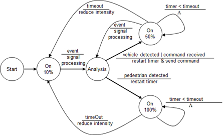
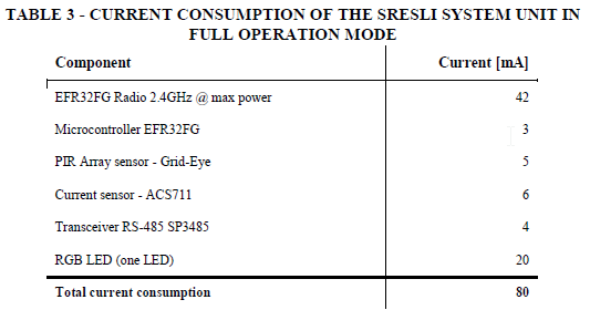
<body><![CDATA[<p align=center><font size="2" face="Verdana, Arial, Helvetica, sans-serif"><b>Figure 10</b>: Task execution using   Round-Robin scheduling scheme.</font></p>     <p align="justify"><font size="2" face="Verdana, Arial, Helvetica, sans-serif">&#9642;&nbsp; <b><i>Light Intensity Control   Application</i></b></font></p>     <p align="justify"><font size="2" face="Verdana, Arial, Helvetica, sans-serif">The light intensity control   application follows 3 different use-cases: pedestrian, vehicle, and   simultaneous pedestrian and vehicle. To control the light, the collected local   and neighbor events are analyzed. The behavior of the light intensity control   is described in the state-machine shown in <a href="#f11">Figure 11</a>. The state machine has   three states representing the percentage of light intensity (i.e., 10%, 50% and   100%). After the initial state, the lights are turned-on to the default 10% of   intensity. When an event is detected by the sensor or communication unit (i.e.,   a command from a neighbor), it is analyzed to identify the aforementioned   use-cases. In the case of a vehicle, the light intensity is increased to 50%   and a command signal is sent to the neighbor (depending on the direction of the   vehicle). Similarly, if pedestrians are detected, the light intensity is   increased to 100%. If pedestrians and vehicles are detected simultaneously, the   control gives priority to pedestrians. In all cases, a timeout is set and on   expiration, the intensity is reduced to the default one if no other event   arrives. This control scheme ensures that the energy consumption is dynamically   adapted to the traffic, thus saving energy when no event happens.</font></p>     <p align=center><font size="2" face="Verdana, Arial, Helvetica, sans-serif"><a name="f11"></a><img border=0 width=447 height=269 id="Imagen 32" src="/img/revistas/riyd/v19n1/a02_image011.png" alt="https://lh6.googleusercontent.com/J0mHNKi6FPdUlFcuylxAwi0RJjzPXnqZFnzkiIsqRrM8nYAdmUWlEXEYDpggzAhTO94RjGiefG_5SMe1-VHZk1ToEJcM6OC4CDKIGWB_T0AMw4e5P6kTCPReEzCRDw"></font></p>     <p align=center><font size="2" face="Verdana, Arial, Helvetica, sans-serif"><b>Figure 11</b>: Light intensity control state-machine.</font><font size="2" face="Verdana, Arial, Helvetica, sans-serif"><b>&nbsp;</b></font></p>     <p align="justify"><font size="2" face="Verdana, Arial, Helvetica, sans-serif"><b>Energy consumption</b></font></p>     <p align="justify"><font size="2" face="Verdana, Arial, Helvetica, sans-serif">The DC-DC power supply of the   SRESLi System Unit provides and measures a fixed stable voltage for all the   electronic components and peripherals inside the device. The operation voltage   of all electronics components is 3.3 V, hence a DC-DC regulator was chosen to   take an input voltage from a higher range and provide a fixed output voltage of   3.3 V.</font></p>     <p align="justify"><font size="2" face="Verdana, Arial, Helvetica, sans-serif">We calculated the current   required by the SRESLi System Unit for the full operation mode (i.e., with PIR   sensor data acquisition, data processing and communication), since this mode is   where the systems consumes current the most. <a href="#t3">Table 3</a> shows the current   consumption of the components used in the SRESLi board. We selected a EFR32FG   Radio 2.4GHz and microcontroller [19], a Grid-Eye PIR Array sensor from   Panasonic [20] and ACS711 Current sensor, a SP3485 RS-485 Transceiver for   serial communication [21] and a LED. The chosen regulator, LT1762 from Linear   Technologies [22], was selected considering the current required by the board   and the output current provided by the integrated circuit and the input voltage   range. The LT1762 is a low-noise low-dropout DC regulator that provides an   output current of 150 mA and supports an input voltage range between 1.8 V and   20 V. The total average current required for the SRESLi System Unit in full   operation mode is of 80 mA, which represents at 3.3 V, a power consumption of   0.26 W. This confirms that our hardware design is highly energy efficient.&nbsp;</font></p>     <p align=center><a name="t3"></a><img src="/img/revistas/riyd/v19n1/a02_table_03.png" width="533" height="280"></p>     <p align="justify"><font size="2" face="Verdana, Arial, Helvetica, sans-serif"><b>3.2 LED street lighting</b></font></p>     ]]></body>
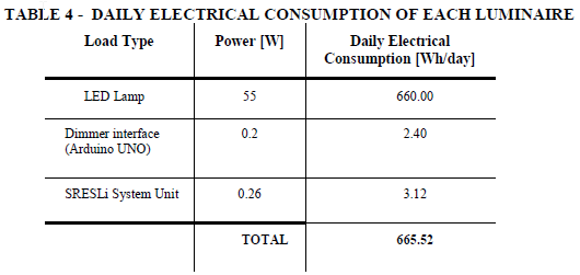
<body><![CDATA[<p align="justify"><font size="2" face="Verdana, Arial, Helvetica, sans-serif">The LED street lighting   subsystem of SRESLi has the following requirements:&nbsp;</font></p>     <p align="justify"><font size="2" face="Verdana, Arial, Helvetica, sans-serif">&#9642;&nbsp;  have the lowest possible power   consumption while providing the required lighting;</font></p>     <p align="justify"><font size="2" face="Verdana, Arial, Helvetica, sans-serif">&#9642;&nbsp; have the ability to regulate   light dimming in order to be controlled by the SRESLi System Unit; and</font></p>     <p align="justify"><font size="2" face="Verdana, Arial, Helvetica, sans-serif">&#9642;&nbsp; comply with the lighting levels   imposed by the Bolivian regulation for street lighting NB 1412001 [23]</font></p>     <p align="justify"><font size="2" face="Verdana, Arial, Helvetica, sans-serif">Based on these requirements, we   selected lamps of type Sword LED Street Light - LEYOND of 50W of power, which   have the best tradeoff between power, availability in the market and cost.   Then, we used the Relux lighting design software [24] to determine important   deployment parameters such as the distance between luminaires and the   installation height where the LED need to be placed. We categorized the road   according to its flow, type, width, and lighting category according to the   public lighting standard. We then run the simulation in Relux, determining the   height and spacing, the geographical location of the poles for the experimental   setup of the system.</font></p>     <p align="justify"><font size="2" face="Verdana, Arial, Helvetica, sans-serif"><b>3.3&nbsp;&nbsp;&nbsp; Photovoltaic system</b></font></p>     <p align="justify"><font size="2" face="Verdana, Arial, Helvetica, sans-serif">The photovoltaic subsystem of   SRESLi includes the daily electrical consumption and the photovoltaic field   parameters, so as to select the most adapted components and the sizing of the   PV system.</font></p>     <p align="justify"><font size="2" face="Verdana, Arial, Helvetica, sans-serif"><b>Electrical Consumption</b></font></p>     <p align="justify"><font size="2" face="Verdana, Arial, Helvetica, sans-serif">To determine the daily   electrical consumption of the system it is important to establish the complete   load of power consumption, the operating period, and the consumption factor. As   a load, we considered both the lamp (with a 55W power consumption), the SRESLi   System Unit (with a 0.26 W power consumption) and the dimmer interface (with a   0.2 W power consumption). The operating time of the system is of 12 hours,   which represents the average daily value (calculated over one year of the   operation) of a conventional public lighting [7, 25]. In addition, it is   important to consider the consumption factor, which corresponds to the   percentage of time that the load will work at maximum electrical power, so as   not to oversize the system.</font></p>     <p align="justify"><font size="2" face="Verdana, Arial, Helvetica, sans-serif"><a href="#t4">Table 4</a> shows the daily   electrical consumption of each LED lamp, the Dimmer Interface (based on an   Arduino UNO device), and the SRESLi System Unit, with a total consumption of   665.52 Wh/day. Based on this result, the sizing of each solar panel gives a   peak power (P<sub>peak</sub>) of 189.93 Wp according to equations (1) and (2)   [35], where, E is the daily energy consumption (i.e., 665.52 Wh/day); &#1394;<sub>general</sub> is the performance ratio or general   performance (i.e., 80% according to [26] which considers a 0.95 PV efficiency, 0.9 battery   efficiency, 0.98 wiring efficiency and 0.95 inverter efficiency);&nbsp; T<sub>min</sub> is the minimal amount of hours per day with solar   radiation (i.e., 4.38 Solar Peak Hours calculated according to [27] with data from the NREL-NASA for the location   coordinates).</font></p>     ]]></body>
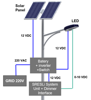
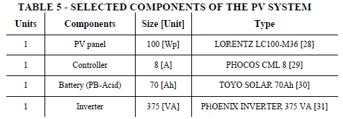
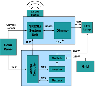
<body><![CDATA[<p align="center"><font size="2" face="Verdana, Arial, Helvetica, sans-serif"><img src="/img/revistas/riyd/v19n1/a02_ecuacion_01.png" width="739" height="37"></font></p>     <p align=center><img src="/img/revistas/riyd/v19n1/a02_ecuacion_02.png" width="741" height="36"></p>     <p align="justify"><font size="2" face="Verdana, Arial, Helvetica, sans-serif">However, since we know that our   system will save energy, using the obtained peak power of 189.93 Wp, represents   a highly oversized value and a high cost. In addition, we would need to measure   the energy saving for an accurate sizing of the required PV system, which is   not possible until the complete installation and measure of the real power   consumption of the system. Fortunately, we can mitigate the oversizing issue,   by taking as reference existing similar intelligent street lighting systems   [5,10,13], which achieve savings between 68% and 82%. We therefore consider a   conservative energy saving of 50% for the sizing of our PV system, resulting in   a final peak power of 94.9 Wp for the component sizing and selection.</font></p>     <p align="center"><a name="t4"></a><img src="/img/revistas/riyd/v19n1/a02_table_04.png" width="530" height="251"><font size="2" face="Verdana, Arial, Helvetica, sans-serif"><b>&nbsp;</b></font></p>     <p align="justify"><font size="2" face="Verdana, Arial, Helvetica, sans-serif"><b>Components Sizing and Selection</b></font></p>     <p align="justify"><font size="2" face="Verdana, Arial, Helvetica, sans-serif">The pilot system is located at   the main campus of the Universidad Privada Boliviana (UPB) in the city of   Cochabamba, Bolivia (at coordinates latitude = -17.399126&ordm; and longitude =   -66.2178536&ordm;). Because the orientation of solar panels would affect solar   radiation parameters for the calculation, we considered the city location in   the southern hemisphere of the globe to calculate the photovoltaic field [27],   resulting in an inclination of 22.17&deg; and an Azimuth of 0&ordm;.&nbsp; The average   value of solar intensity in the pilot coordinates is about 600 W/m2 [9].</font></p>     <p align="center"><a name="t5"></a><img src="/img/revistas/riyd/v19n1/a02_table_05.png" width="493" height="172"></p>     <p align="justify"><font size="2" face="Verdana, Arial, Helvetica, sans-serif">Based on the previously   calculated daily electrical consumption, the photovoltaic field   characteristics, and the local solar intensity, we calculated the components   sizing using the conventional sizing method [35], which is shown in <a href="#t5">Table 5</a>, for   each pole.</font></p>     <p align="justify"><font size="2" face="Verdana, Arial, Helvetica, sans-serif"><b>System Design</b></font></p>     <p align="justify"><font size="2" face="Verdana, Arial, Helvetica, sans-serif">Once the sizing of the PV   system components was set, we include the integration with the SRESLi System   Unit and a connection to the conventional 220V electric grid (for backup   energy). <a href="#f12">Figure 12</a> shows the deployment diagram for each light pole of the   system.</font></p>     ]]></body>
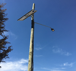
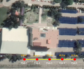
<body><![CDATA[<p align="center"><font size="2" face="Verdana, Arial, Helvetica, sans-serif"><a name="f12"></a><img border=0 width=295 height=324 id="Imagen 30" src="/img/revistas/riyd/v19n1/a02_image014.png" alt="https://lh3.googleusercontent.com/2slZNSneE6Nm4yrGaPzeaeHn6kChlGWGkrYcbCgjuJSJFgaPnqOEd0BEXFVMRzC6a-4tuiNkZ_HRKol-oXzmjjm054FXWdD9ABBGze6yNSTA4C8vJ-LgYI7VQjASQA"></font></p>     <p align=center><font size="2" face="Verdana, Arial, Helvetica, sans-serif"><b>Figure 12: </b>Deployment diagram for each light pole.</font></p>     <p align="justify"><font size="2" face="Verdana, Arial, Helvetica, sans-serif">Following the proposed   deployment and integration scheme, we designed the final system architecture   (see <a href="#f13">Figure 13</a>), where the voltage levels of each connection are shown (whether   it is of 12 V, 220 V or electronic control). The figure shows a switch that   allows to select the energy source which can be autonomous (i.e., from the PV   system) or the conventional electric grid. The switch is operated manually, and   the system uses the conventional electric grid, in the case of climate   conditions, not allowing to have enough solar intensity. The PV system, stores   energy in the battery, which requires a changer controller that handles the   current entering the battery, as well as the energy that is used by the electrical   loads (i.e, the LED lamp, the SRESLi System Unit, and the Dimmer Interface).   Because the voltage that uses the LED luminaire is of 220 VAC, and the battery   provides 12 VDC, we use a DC-AC inverter connected to the battery through the   charge controller. Furthermore, to dim the LED luminaire intensity, a   Pulse-Width Modulation (PWM) is required in a 0 to 10 V interval, which   corresponds to a 0 to 100% light intensity. The SRESLi System Unit sends a   digital control signal through a RS485 serial communication, that needs to be   converted to a PWM, which is done by the Dimmer Interface based on an Arduino   UNO and an additional electronic circuit using a NPN BC639 [32] (not shown in   the figure). Finally, depending on the event detected by the sensor, the decision   is sent to the neighbor SRESLi System Units, using the previously described   communication protocol through the 2.4 GHz Radio.&nbsp;</font></p>     <p align=center><font size="2" face="Verdana, Arial, Helvetica, sans-serif"><a name="f13"></a><img border=0 width=375 height=364 id="Imagen 29" src="/img/revistas/riyd/v19n1/a02_image015.png" alt="https://lh6.googleusercontent.com/neiNdKPyMUH-ivjR-rFnbjW5l-Eu3gy-qctIESM9jZDMnNnCFGSppgoeXNFxFWUU2JN5fV_rVrB5kFMGMIDG9Ght4eHVzkOVrKbwqQxL6v99V4eP0ZHjN8orm2cf0w"></font></p>     <p align=center><font size="2" face="Verdana, Arial, Helvetica, sans-serif"><b>Figure 13:</b> Complete system&rsquo;s architecture diagram.</font></p>     <p align="justify">&nbsp;</p>     <p align="justify"><font size="3" face="Verdana, Arial, Helvetica, sans-serif"><b>4.&nbsp;&nbsp;&nbsp;&nbsp; EXPERIMENTAL SETUP AND RESULTS</b></font></p>     <p align="justify"><font size="2" face="Verdana, Arial, Helvetica, sans-serif">A SRESLi pilot was implemented   at Universidad Privada Boliviana as the experimental setup to measure lighting   levels, energy generation and power consumption. The pilot includes five light   poles deployed on the campus back road, a poorly illuminated road with medium   to low vehicular and pedestrian traffic. The light poles had a 15m distance   between each other and the lamps were fixed at a height of 7m. <a href="#f14">Figure 14</a> shows   the poles distribution and <a href="#f15">Figure 15</a> shows the implementation of one light   pole.&nbsp;</font></p> <table width="578" border="0" align="center">   <tr>     <td width="300">    <p align="center"><a name="f14"></a><img src="/img/revistas/riyd/v19n1/a02_image016.png" width="288" height="238"></p>             <p align="center"><font size="2" face="Verdana, Arial, Helvetica, sans-serif"><b>Figure 14:</b> Pilot system deployment scheme.</font></p></td>     <td width="268">    ]]></body>
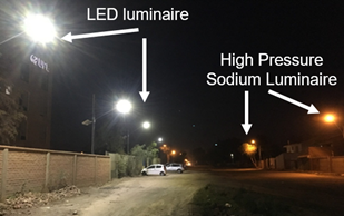
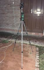
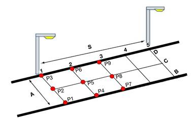
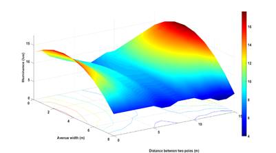
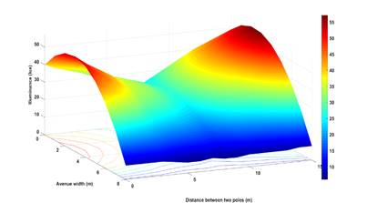
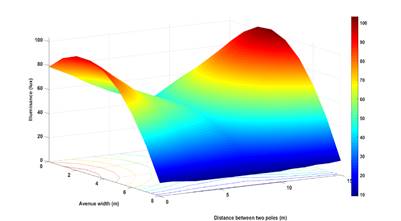
<body><![CDATA[<p align="center"><a name="f15"></a><img src="/img/revistas/riyd/v19n1/a02_image017.png" width="253" height="237"></p>             <p align="center"><font size="2" face="Verdana, Arial, Helvetica, sans-serif"><b>Figure 15:</b> Implemented light pole.</font></p></td>   </tr> </table>     <p align="justify"><font size="2" face="Verdana, Arial, Helvetica, sans-serif"><a href="#f16">Figure 16</a> shows the complete   pilot system running at its maximum intensity during the night. The figure   shows a comparison between our LED-based pilot (on the left) w.t.r. the   existing street lighting based on High Pressure Sodium - HPS (on the right). We   can see a clear improvement in the visibility and a homogeneity of lighting in   the left-side part of the figure. Also, the LED-based street lighting   eliminates the monochromatic black appearance of object illuminated by the HPS,   thus providing a much better variety of high Color Rendering Index (CRI)<a href="#_ftn4" name="_ftnref4" title="">[4]</a>.</font></p> <table width="450" border="0" align="center">   <tr>     <td>    <p align="center"><a name="f16"></a><img src="/img/revistas/riyd/v19n1/a02_image018.png" width="309" height="194"></p></td>   </tr>   <tr>     <td valign="top">    <p align="center"><font size="2" face="Verdana, Arial, Helvetica, sans-serif"><b>Figure 16:</b></font><font size="2" face="Verdana, Arial, Helvetica, sans-serif">The complete deployed pilot system, comparing LED luminaires and High-Pressure Sodium luminaires.</font></p>     </td>   </tr> </table>     <p align="justify"><font size="2" face="Verdana, Arial, Helvetica, sans-serif"><b>4.1&nbsp;&nbsp;&nbsp;&nbsp;&nbsp; Lighting levels</b></font></p>     <p align="justify"><font size="2" face="Verdana, Arial, Helvetica, sans-serif">In order to measure the   lighting distribution between the poles, we measured the illuminance in lux at   each point of a measuring matrix using a luxometer<a href="#_ftn5" name="_ftnref5" title="">[5]</a> attached to a   tripod, so as to hold the sensor perfectly parallel to the ground as shown in <a href="#f17">Figure 17</a>. <a href="#f18">Figure 18</a> shows the matrix with 15 points of measurements. It divides   the 15 meters of distance between the poles (S) into 5 segments and divides the   street width (A) into three segments (B, C, and D). <a href="#f19">Figures 19</a>, <a href="#f20">20</a> and <a href="#f21">21</a> show   the spatial distribution for a 10%, 50% and 100% lighting level, respectively.   We can observe in these spatial distributions, that the illuminance at the   ground level between the poles, do not create gaps. This confirms the   homogeneous LED-based lighting, shown in the left-side of <a href="#f16">Figure 16</a>.</font></p> <table width="673" border="0" align="center">   <tr>     <td width="251">    <p align="center"><font size="2" face="Verdana, Arial, Helvetica, sans-serif"><a name="f17"></a><img border=0 width=150 height=235 id="Imagen 22" src="/img/revistas/riyd/v19n1/a02_image019.png" alt="https://lh5.googleusercontent.com/Q4ycuZGFMSwYM-EtuV3zjDFKms4kszBIK3rRNgSuJSRXSSBZ2h8psSSEZmpZyxuVeAarTiiaaCqx_sx_dXFw7HUwrZGeYN0pPqIRCONrGMHnm2ToTnlAAtLIbr7WSRdrnxblbRs"></font></p>             <p align="center"><font size="2" face="Verdana, Arial, Helvetica, sans-serif"><b>Figure 17: </b>Luxometer on tripod. &nbsp;</font></p></td>     <td width="412">    <p align="center"><font size="2" face="Verdana, Arial, Helvetica, sans-serif"><a name="f18"></a><img border=0 width=380 height=236 id="Imagen 20" src="/img/revistas/riyd/v19n1/a02_image020.jpg" alt="https://lh4.googleusercontent.com/ME1JR5zHorNxT_971GTThtgLxTCuc3Kd2tSgQDBS8VbHFGGvwx9DJmxmwVSTCfsXwNJTeiY1wGnkt4RbffsxEW78Qv_qXljVDU_Z1UJBkIGTIynyyhlWa55F9r0RxA"></font></p>             ]]></body>
<body><![CDATA[<p align="center"><font size="2" face="Verdana, Arial, Helvetica, sans-serif"><b>Figure           18: </b>Illuminance measurements matrix.</font></p></td>   </tr> </table>     <p align=center><font size="2" face="Verdana, Arial, Helvetica, sans-serif">&nbsp;&nbsp;&nbsp;&nbsp;&nbsp;&nbsp;&nbsp;&nbsp;&nbsp;&nbsp;&nbsp; &nbsp;</font><font size="2" face="Verdana, Arial, Helvetica, sans-serif">&nbsp;&nbsp;&nbsp;&nbsp;&nbsp;&nbsp;&nbsp;&nbsp;&nbsp;&nbsp;&nbsp;&nbsp;&nbsp;&nbsp;&nbsp;&nbsp;&nbsp;&nbsp;&nbsp;&nbsp;&nbsp;&nbsp;&nbsp;</font></p>     <p align=center><font size="2" face="Verdana, Arial, Helvetica, sans-serif"><b><a name="f19"></a><img border=0 width=401 height=223 id="Imagen 19" src="/img/revistas/riyd/v19n1/a02_image021.jpg" alt="https://lh5.googleusercontent.com/FTPLqAbEmoRB0Jf92mteFFwdDRO6oWsdjmEIo5SejFEGMoM_onjyR0Dxf-3ItwhtWiYDa5LBIxQp42cJtIGZ0-xH4HMAyYmqrGjAG6sqhiiQI2oNz4kmfwfDnkP4aA"></b></font></p>     <p align=center><font size="2" face="Verdana, Arial, Helvetica, sans-serif"><b>Figure 19: </b>Spatial distribution of   illuminance of the system at 10% lighting level.</font></p>     <p align=center><font size="2" face="Verdana, Arial, Helvetica, sans-serif"><b><a name="f20"></a><img border=0 width=403 height=223 id="Imagen 18" src="/img/revistas/riyd/v19n1/a02_image022.jpg" alt="https://lh5.googleusercontent.com/XvU9XjCWvTvOjckz1vlTebE9d2E4VMHMgHrzv7yJolQXdLffTHBECzQysXJZygbI4LEbQssQOIcJkLM6ZjQ2RqCgirfu50gjnLY57zHj85tasdcnym1X1FzJp6DGxw"></b></font></p>     <p align=center><font size="2" face="Verdana, Arial, Helvetica, sans-serif"><b>Figure 20: </b>Spatial distribution of   illuminance of the system at 50% lighting level.</font></p>     <p align="center">&nbsp;</p>     <p align=center><font size="2" face="Verdana, Arial, Helvetica, sans-serif"><a name="f21" id="f21"></a><img border=0 width=401 height=221 id="Imagen 16" src="/img/revistas/riyd/v19n1/a02_image023.jpg" alt="https://lh3.googleusercontent.com/P4yKgMb2FjABG5SnDBJsXzuvBmG3JOnVqMxyskVpkintx5w7CV9KCbUkkcAGpZWCp2HpTbOs1j2j4lpoC971nGDeWUz9vvV86s2eAWmtCvFhyW3uWOsPTJDndPPAdQ"></font></p>     <p align=center><font size="2" face="Verdana, Arial, Helvetica, sans-serif"><b>Figure 21: </b>Spatial distribution of   illuminance of the system at 100% lighting level.</font></p>     <p align="justify"><font size="2" face="Verdana, Arial, Helvetica, sans-serif">In order to determine whether   the illuminance of our pilot complies with Bolivian regulations for street   lighting [23], we measured the average illuminance applying the nine-points method [33,34] in the measurement matrix. We calculated the average illuminance   in the three lighting levels (10%, 50% and 100%) in which the system operates.   The measurements were made between light poles that are not those in the   border.&nbsp;</font></p>     ]]></body>
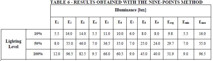
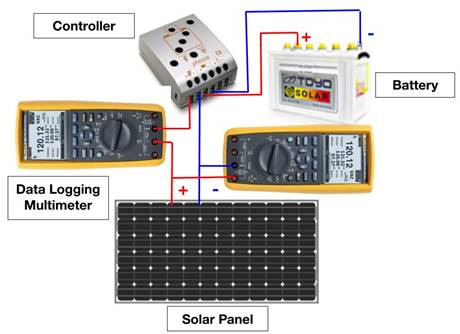
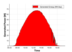
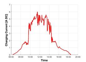
<body><![CDATA[<p align="justify"><font size="2" face="Verdana, Arial, Helvetica, sans-serif"><a href="#t6">Table 6</a> shows the results obtained with the nine-point   method, where <b>E<sub>i</sub></b> is the illuminance of each   measured point (i = 1...9), <b>E<sub>avg</sub></b> is the average illuminance, and <b>E<sub>min</sub></b> and <b>E<sub>max</sub></b> are the minimum and maximum illuminance,   respectively. The average illuminance calculated for each lighting level is as   follows: 9.8 lux for a 10% lighting level, 29.7 lux for a 50% lighting level,   and 51.9 lux for a 100% lighting level. These results confirm that, even at the   lowest level of intensity, the system operates according to the Bolivian   regulations for street lighting, which requires an average illuminance between   5 and 10 lux [23].</font></p>     <p align="center"><a name="t6"></a><img src="/img/revistas/riyd/v19n1/a02_table_06.png" width="686" height="199"></p>     <p align="justify"><font size="2" face="Verdana, Arial, Helvetica, sans-serif"><b>4.2&nbsp;&nbsp;&nbsp;&nbsp;&nbsp; Power generation, consumption   and intelligent control</b></font></p>     <p align="justify"><font size="2" face="Verdana, Arial, Helvetica, sans-serif">Once the pilot was deployed and   the spatial distribution of illuminance were measured, we proceed to measure   the power generation of the PV system, the consumption of the luminaires to   validate the energy efficiency thanks to the intelligent control of the SRESLi   System Unit.</font></p>     <p align="justify"><font size="2" face="Verdana, Arial, Helvetica, sans-serif"><b>a.&nbsp;&nbsp;&nbsp;&nbsp; Power Generation</b></font></p>     <p align="justify"><font size="2" face="Verdana, Arial, Helvetica, sans-serif">To determine whether the PV   system generates enough electricity to work properly (for both the lighting and   electronic control system), we collected power generation measurements using   two data logging multimeters<a href="#_ftn6" name="_ftnref6" title="">[6]</a>.   One multimeter was used to take current measures and the other to take voltage   measures as shown in <a href="#f22">Figure 22</a>. Under this scheme, we used a 5 minutes   measurement interval throughout the entire day in each of the 5 poles.<b>&nbsp;&nbsp;</b></font></p>     <p align=center><font size="2" face="Verdana, Arial, Helvetica, sans-serif"><a name="f22"></a><img border=0 width=460 height=334 id="Imagen 15" src="/img/revistas/riyd/v19n1/a02_image024.jpg" alt="https://lh3.googleusercontent.com/qHNIgkTGQCw8IEh_PWyBEspDOnYjBvUQeC55uqpgsC0H3_xnDs18m-oCoZf3ClGbuMF1fIWXvDT8VVYDT1u3-59EG-JI5StJ5Cr6yExBqPrK3tv2jHpq82-2YHpSJA"></font></p>     <p align=center><font size="2" face="Verdana, Arial, Helvetica, sans-serif"><b>Figure 22:</b> Power generation measurement   scheme.</font></p>     <p align="justify"><font size="2" face="Verdana, Arial, Helvetica, sans-serif"><a href="#f23">Figure 23</a> (left) shows the   average power generation for one PV panel in each pole throughout a day (12   hours). The average generated energy is represented by the area under the   curve, and is 457.1 Wh. <a href="#f23">Figure 23</a> (right) shows the measured current flow to   the battery, allowing to determine a stored energy of 359.8 Wh. The amount of   generated energy is clearly not enough to power all the loads of the luminaire   (i.e., LED lamp, SRESLi System Unit, and Dimmer Interface) for 12 hours   operation time, which requires 665.52 Wh/day (see <a href="#t4">Table 4</a>). We therefore   proceed to measure the actual power consumption in two scenarios:</font></p>     <p align="justify"><font size="2" face="Verdana, Arial, Helvetica, sans-serif">&#9642;&nbsp; without the SRESLi System Unit:   to determine the maximum amount of time that the stored energy allows to power   one street lighting luminaire at its full intensity; and&nbsp;</font></p>     ]]></body>
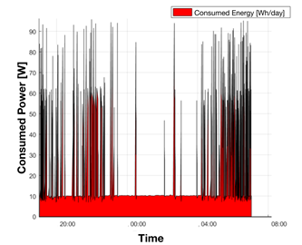
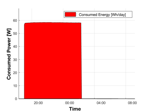
<body><![CDATA[<p align="justify"><font size="2" face="Verdana, Arial, Helvetica, sans-serif">&#9642;&nbsp; with the SRESLi System Unit: to   show the intelligent adaptive lighting with energy efficiency, and that the   stored energy is enough to operate more than 12 hours.</font></p>     <p align=center><font size="2" face="Verdana, Arial, Helvetica, sans-serif"><a name="f23"></a><img border=0 width=285 height=204 id="Imagen 14" src="/img/revistas/riyd/v19n1/a02_image025.png" alt="https://lh3.googleusercontent.com/xnwqMPZ3d9MJR4P5R_amzchVC3PT3RAQbNB33FoHzkkyNC-NJIYhMHlOp88WW1HgQkllc2N_jL-A9rlgKxpqUF9uEB_78LiyxoKYYyZS3st6Yxa3Z_rE4p8z-J3sgw"><img border=0 width=276 height=199 id="Imagen 13" src="/img/revistas/riyd/v19n1/a02_image026.jpg" alt="https://lh6.googleusercontent.com/t5RziAERYtwgo4pkobuAAwlI1W17Ta5O6cn0vqx_DOMI7bRIG1AYPoeD6vImiA0DKF4mod7a7UvpcnINKKsJHO_tXJ4Z21IVDpAiI40d1RQZU7Sk3tHT5_fOvDXC5A"></font></p>     <p align="center"><font size="2" face="Verdana, Arial, Helvetica, sans-serif"><b>Figure 23: </b>Average generated power (left)   and the charging current circulating to a battery (right), throughout a day of   one PV panel.</font></p>     <p align="justify"><font size="2" face="Verdana, Arial, Helvetica, sans-serif"><b>b.&nbsp;&nbsp;&nbsp; Power consumption without the   SRESLi System Unit</b></font></p>     <p align="justify"><font size="2" face="Verdana, Arial, Helvetica, sans-serif">We measure the power   consumption of the system without the SRESLi in one street lighting luminaire   at 100% of its capacity over a full night. A data logging multimeter is used to   measure the AC current consumption using a default 5-minute intervals, but also   registering any sudden current change in between the intervals to identify all   patterns of consumption changes. <a href="#f24">Figure 24</a> shows the total consumed power which   drained the battery in 6.5 hours, covering only half of the required energy (at   100%). Thus, through this experimental measurement, we obtain that the total   consumption in 12 hours is about 665 W, which is closed to the previously   estimated value of 665.52 Wh/day of 12 hours (see <a href="#t4">Table 4</a>).&nbsp;</font></p>     <p align=center><font size="2" face="Verdana, Arial, Helvetica, sans-serif"><a name="f24"></a><img border=0 width=496 height=371 id="Imagen 11" src="/img/revistas/riyd/v19n1/a02_image027.png" alt="https://lh3.googleusercontent.com/ah3vWurpXTeAzTq2JLu7I4wNwFaCJf7LFKzllBqOIf24hnJpN9KIc7gTREK1JgJR4nZ1hIViuC0depOHzHdLTqoSMawr_LXqC6kwABfLxfaQH6kBn4dTjnzEXkp0Nw"></font></p>     <p align="center"><font size="2" face="Verdana, Arial, Helvetica, sans-serif"><b>Figure 24:</b>&nbsp; Power consumption for   one luminaire throughout the night without the SRESLi System Unit.</font></p>     <p align="justify"><font size="2" face="Verdana, Arial, Helvetica, sans-serif"><b>c.&nbsp;&nbsp;&nbsp;&nbsp;&nbsp;&nbsp;&nbsp; Power   consumption with the SRESLi System Unit</b></font></p>     <p align="justify"><font size="2" face="Verdana, Arial, Helvetica, sans-serif">The final set of measurements   focused on the power consumption with the SRESLi System Unit using a data   logging multimeter as described previously. <a href="#f25">Figure 25</a> shows the average power   consumption over the night (from 18:00 to 06:00) for one luminaire for one   week, with the pedestrian and vehicle detection enabled. We can observe   consumption peaks when pedestrian or vehicles are detected and valleys when low   activity happens (e.g, between 23:00 and 04:00). Furthermore, the peaks for   pedestrians are higher than those for vehicles (of around 90 W at 100% of   intensity and 60 W at 50% of intensity, respectively). Since the nominal power   consumption of one luminaire is of 665.52 Wh/day in 12 hours operation (see <a href="#t4">Table 4</a>), the instantaneous power consumption should be of 55.46 W at 100% of   intensity. This difference can be explained by initial power required to start   the LED electronic driver, which results in a cumulated peak that is higher   than the nominal power consumption.&nbsp;</font></p>     <p align="justify">&nbsp;</p>     ]]></body>
<body><![CDATA[<p align=center><font size="2" face="Verdana, Arial, Helvetica, sans-serif">&nbsp;<b><a name="f25"></a><img border=0 width=333 height=270 id="Imagen 10" src="/img/revistas/riyd/v19n1/a02_image028.png" alt="https://lh3.googleusercontent.com/vOqaN5LgeozyvD1GUU3Kceggb64etq1ORNa8VJt57h0HlHYMhbAIhXQQl6DFuNYQ1SPPcQJf0-6pO_8inaC1vLfzmNOiTbPPj8iHXznavXr6P_7CUCD2y5DGHPQq4w"></b></font></p>     <p align=center><font size="2" face="Verdana, Arial, Helvetica, sans-serif"><b>Figure 25: </b>Power consumption for one   luminaire throughout the night with SRESLi.</font></p>     <p align="justify"><font size="2" face="Verdana, Arial, Helvetica, sans-serif">Additionally, at 10% of   intensity the power consumption should be of 5.54 W. However, <a href="#f25">Figure 25</a> shows   that, at this default lowest intensity, the power consumption is close to 10 W.   This can be explained by the fact that the light intensity is not linearly   proportional to the power consumption, because it is optimized to the maximum   of its nominal power. The measured current by the data logging multimeter at   10% of light intensity is of 0.04 A, which corresponds to a power of 8.8 W at   220 VAC (close the 10 W observed in the figure).&nbsp;</font></p>     <p align="justify"><font size="2" face="Verdana, Arial, Helvetica, sans-serif">Finally, the overall measured   power consumption of one luminaire with the SRESLi System Unit throughout the   12 operating hours (i.e., the area under the curve in <a href="#f25">Figure 25</a>), is of 181   Wh/day. Thus, by comparing this value to the power consumption without any   intelligent control system (i.e., 665.52 Wh/day shown in <a href="#t4">Table 4</a>), we   demonstrate an energy saving of 72.8%, thanks to the adaptive lighting and low   consumption of the SRESRLi System Unit. We therefore can either keep the   estimated 100 Wp PV panel (see Section 3.3) to reuse the surplus power   (e.g., injecting it to the grid) or we could re-size the PV system to reduce   the power peak of the PV panel, thus minimize the cost of the system. These   results encourage us for future work on scaling up the SRESLi system, from a   pilot towards a widely deployed street lighting system, which may require a   more advanced communication protocol, to include monitoring data.</font></p>     <p align="justify">&nbsp;</p>     <p align="justify"><font size="3" face="Verdana, Arial, Helvetica, sans-serif"><b>5.&nbsp;&nbsp;&nbsp;&nbsp; CONCLUSIONS</b></font></p>     <p align="justify"><font size="2" face="Verdana, Arial, Helvetica, sans-serif">This article describes the   design, development, and testing of the Smart Renewable Energy Street Lighting   System (SRESLi) as a solution to address the problems related to the   traditional street lighting systems. The proposed system was designed with an energy   efficiency approach on each stage of the process. Our pilot system shows that   the energy savings when using the SRESLi wireless embedded electronic control   on a medium- to low-traffic road can be up to 72.8%. Additionally, the SRESLi   appears to be an option to provide reliable street lighting for peripheral   areas where there is no grid access. Furthermore, surplus power, as a result   from energy savings, could be either injected to the grid, in urban areas, or   be used for other applications (home lighting, refrigeration, charging mobile   devices, and others) in locations with no electrical grid access.</font></p>     <p align="justify">&nbsp;</p>     <p align="justify"><font size="3" face="Verdana, Arial, Helvetica, sans-serif"><b>6.&nbsp;&nbsp;&nbsp;&nbsp; ACKNOWLEDGMENTS</b></font></p>     <p align="justify"><font size="2" face="Verdana, Arial, Helvetica, sans-serif">This work was partially funded   by Universidad Privada Boliviana (Bolivia) and the RETECA Foundation   (Switzerland).</font></p>     ]]></body>
<body><![CDATA[<p align="justify">&nbsp;</p>     <p align="justify"><font size="3" face="Verdana, Arial, Helvetica, sans-serif"><b>7.&nbsp;&nbsp;&nbsp;&nbsp; REFERENCES</b></font></p>     <p align="justify"><font size="2" face="Verdana, Arial, Helvetica, sans-serif">[1]&nbsp;&nbsp;&nbsp; The   Royal Society for the Prevention of Accidents, &ldquo;Road Safety Information -   Street Lighting and Road Safety,&rdquo; Edgbaston, Birmingham, 2018.</font></p>     <p align="justify"><font size="2" face="Verdana, Arial, Helvetica, sans-serif">[2]&nbsp;&nbsp;&nbsp; R.   Beyer and K. Ker, &ldquo;Street lighting for preventing road traffic injuries,&rdquo; <i>Cochrane     Database Syst. Rev.</i>, no. 1, pp. 2009&ndash;2011, 2009.</font></p>     <p align="justify"><font size="2" face="Verdana, Arial, Helvetica, sans-serif">[3] &nbsp;&nbsp; B.   Welsh and D. Farrington, &ldquo;Effects of improved street lighting on crime,&rdquo; <i>Campbell     Syst. Rev.</i>, vol. 4, no. 13, 2008.</font></p>     <p align="justify"><font size="2" face="Verdana, Arial, Helvetica, sans-serif">[4]&nbsp;&nbsp;&nbsp; R.   Steinbach, C. Perkins, L. Tompson, S. Johnson, B. Armstrong, J. Green, C.   Grundy, P. Wilkinson, and P. Edwards, &ldquo;The effect of reduced street lighting on   road casualties and crime in England and Wales: Controlled interrupted time   series analysis,&rdquo; <i>J. Epidemiol. Community Health</i>, vol. 69, no. 11, pp.   1118&ndash;1124, 2015.</font></p>     <p align="justify"><font size="2" face="Verdana, Arial, Helvetica, sans-serif">[5]&nbsp;&nbsp;&nbsp; G.   Shahzad, H. Yang, A. W. Ahmad, and C. Lee, &ldquo;Energy-Efficient Intelligent Street   Lighting System Using Traffic-Adaptive Control,&rdquo; <i>IEEE Sens. J.</i>, vol. 16,   no. 13, pp. 5397&ndash;5405, 2016.</font></p>     <p align="justify"><font size="2" face="Verdana, Arial, Helvetica, sans-serif">[6]&nbsp;&nbsp;&nbsp; CNDC,   &ldquo;Principales Sistemas El&eacute;ctricos,&rdquo; <i>Reportes Comit&eacute; Nacional de Despacho de     Carga</i>, 2018. [Online].   Available: <a href="http://www.cndc.bo/sin/index.php" target="_blank">http://www.cndc.bo/sin/index.php</a>. [Accessed: 12-Jul-2018].</font></p>     <p align="justify"><font size="2" face="Verdana, Arial, Helvetica, sans-serif">[7]&nbsp;&nbsp;&nbsp; C.   R. B. S. Rodrigues, P. S. 0. Almeida, G. M. Soares, J. M. Jorge, D. P. Pinto, and H. A. C.   Braga, &ldquo;An experimental comparison between different technologies arising for   public lighting: LED luminaires replacing high pressure sodium lamps,&rdquo; in <i>Proceedings     - ISIE 2011: 2011 IEEE International Symposium on Industrial Electronics</i>,   pp. 141&ndash;146, 2011.</font></p>     <p align="justify"><font size="2" face="Verdana, Arial, Helvetica, sans-serif">[8]&nbsp;&nbsp;&nbsp; M.   Barman, S. Mahapatra, D. Palit, and M. K. Chaudhury, &ldquo;Energy for Sustainable   Development Performance and impact evaluation of solar home lighting systems on   the rural livelihood in Assam, India,&rdquo; <i>Energy Sustain. Dev.</i>, vol. 38, pp. 10&ndash;20, 2017.</font></p>     ]]></body>
<body><![CDATA[<p align="justify"><font size="2" face="Verdana, Arial, Helvetica, sans-serif">[9]&nbsp;&nbsp;&nbsp; M. Lucano, I. Fuentes,   and S. Avil&eacute;s, &ldquo;Mapa Solar de Bolivia,&rdquo; 2010. [Online]. Available: <a href="http://www.energetica.org.bo/energetica/pdf/publicaciones/mapa_solar.pdf" target="_blank">http://www.energetica.org.bo/energetica/pdf/publicaciones/mapa_solar.pdf</a>.   [Accessed: 07-Feb-2019].</font></p>     <p align="justify"><font size="2" face="Verdana, Arial, Helvetica, sans-serif">[10]&nbsp; M.   Magno, T. Polonelli, L. Benini, E. Popovici, and S. Member, &ldquo;A Low Cost ,   Highly Scalable Wireless Sensor Network Solution to Achieve Smart LED Light   Control for Green Buildings,&rdquo; vol. 15, no. 5, pp. 2963&ndash;2973, 2015.</font></p>     <p align="justify"><font size="2" face="Verdana, Arial, Helvetica, sans-serif">[11]&nbsp; P.   C. Veena, P. Tharakan, and H. Haridas, &ldquo;Smart Street Light System based on   Image Processing&rdquo; in <i>International Conference on Circuit, Power and     Computing Technologies [ICCPCT]</i>, 2016.</font></p>     <p align="justify"><font size="2" face="Verdana, Arial, Helvetica, sans-serif">[12]&nbsp; S.   Siregar, &ldquo;Solar Panel and Battery Street Light Monitoring System Using GSM   Wireless Communication System,&rdquo; in <i>2nd International Conference on     Information and Communication Technology (ICoICT)</i>, pp. 272&ndash;275, 2014.</font></p>     <p align="justify"><font size="2" face="Verdana, Arial, Helvetica, sans-serif">[13]&nbsp; M.   Swati and R. Parekar, &ldquo;An Intelligent System for Monitoring and Controlling of   Street Light using GSM Technology,&rdquo; in <i>International Conference on     Information Processing (ICIP)</i>, pp. 604&ndash;609, 2015.</font></p>     <p align="justify"><font size="2" face="Verdana, Arial, Helvetica, sans-serif">[14]&nbsp; A.   Kov&aacute;cs, R. B&aacute;tai, B. C. Cs&aacute;ji, P. Dud&aacute;s, B. H&aacute;y, G. Pedone, T. R&eacute;v&eacute;sz, and J.   V&aacute;ncza, &ldquo;Intelligent control for energy-positive street lighting,&rdquo; <i>Energy</i>,   vol. 114, pp. 40&ndash;51, 2016.</font></p>     <p align="justify"><font size="2" face="Verdana, Arial, Helvetica, sans-serif">[15]&nbsp; IEEE   Standards Association, <i>IEEE Standard for Local and metropolitan area     networks &mdash; Part 15 . 4&#8239;: Low-Rate Wireless Personal Area Networks (LR-WPANs)</i>.   New York, US: The Institute of Electrical and Electronics Engineers, Inc.,   2011.</font></p>     <p align="justify"><font size="2" face="Verdana, Arial, Helvetica, sans-serif">[16]&nbsp; IHS Markit   Standards Store, &ldquo;ANSI TIA/EIA-485-A Electrical Characteristics of Generators   and Receivers for Use in Balanced Digital Multipoint Systems.&rdquo; [Online].   Available: <a href="https://global.ihs.com/doc_detail.cfm?&document_name=TIA-485" target="_blank">https://global.ihs.com/doc_detail.cfm?&amp;document_name=TIA-485</a> [Accessed: 07-Jan-2019].</font></p>     <p align="justify"><font size="2" face="Verdana, Arial, Helvetica, sans-serif">[17]&nbsp; IHS   Markit Standards Store, &ldquo;TSB89 Application Guidelines for TIA/EIA-485.&rdquo;   [Online]. Available: <a href="https://global.ihs.com/doc_detail.cfm?&item_s_key=00293218" target="_blank">https://global.ihs.com/doc_detail.cfm?&amp;item_s_key=00293218</a> [Accessed:   07-Jan-2018].</font></p>     <p align="justify"><font size="2" face="Verdana, Arial, Helvetica, sans-serif">[18]&nbsp; Silicon Labs,   &ldquo;AN0002.1: EFM32 and EFR32 Wireless Gecko Series 1 Hardware Design   Considerations,&rdquo; 2016. [Online]. Available: <a href="https://www.silabs.com/documents/public/application-notes/an0002.1-efr32-efm32-series-1-hardware-design-considerations.pdf" target="_blank">https://www.silabs.com/documents/public/application-notes/an0002.1-efr32-efm32-series-1-hardware-design-considerations.pdf</a>.   [Accessed: 01-Jun-2017].</font></p>     ]]></body>
<body><![CDATA[<p align="justify"><font size="2" face="Verdana, Arial, Helvetica, sans-serif">[19]&nbsp; Silicon Labs,   &ldquo;EFR32FG12 Flex Gecko Proprietary Protocol SoC Family Data Sheet,&rdquo; 2016.   [Online]. Available: <a href="https://www.silabs.com/documents/public/data-sheets/efr32fg1-datasheet.pdf" target="_blank">https://www.silabs.com/documents/public/data-sheets/efr32fg1-datasheet.pdf</a>.   [Accessed: 01-Jun-2017].</font></p>     <p align="justify"><font size="2" face="Verdana, Arial, Helvetica, sans-serif">[20]&nbsp; Panasonic,   &ldquo;Infrared array sensor grid-eye.&rdquo; [Online]. Available: <a href="https://industrial.panasonic.com/ww/products/sensors/built-in-sensors/grid-eye" target="_blank">https://industrial.panasonic.com/ww/products/sensors/built-in-sensors/grid-eye</a>.   [Accessed: 06-Mar-2017].</font></p>     <p align="justify"><font size="2" face="Verdana, Arial, Helvetica, sans-serif">[21]&nbsp; MaxLinear,   &ldquo;SP3485 - 3.3 V Low Power Half-duplex Rs-485 Transceiver with 10Mbps Data   Rate.&rdquo; [Online]. Available: <a href="https://www.maxlinear.com/ds/sp3485.pdf" target="_blank">https://www.maxlinear.com/ds/sp3485.pdf</a> .   [Accessed: 07-Jan-2019].</font></p>     <p align="justify"><font size="2" face="Verdana, Arial, Helvetica, sans-serif">[22]&nbsp; Linear   Technologies, &ldquo;LT1762 Series - 150 mA, Low Noise LDO Micropower Regulators,&rdquo; <i>REV     A</i>, 2017. [Online].   Available: <a href="http://www.farnell.com/datasheets/42651.pdf" target="_blank">http://www.farnell.com/datasheets/42651.pdf</a>.</font></p>     <p align="justify"><font size="2" face="Verdana, Arial, Helvetica, sans-serif">[23]&nbsp; IBNORCA,   &ldquo;NB 1412001:2 Alumbrado p&uacute;blico - Reglas generales y especificaciones   t&eacute;cnicas.&rdquo; 2013.</font></p>     <p align="justify"><font size="2" face="Verdana, Arial, Helvetica, sans-serif">[24]&nbsp; Relux,   &ldquo;ReluxDesktop&rdquo; [Online]. Available: <a href="https://reluxnet.relux.com/en/relux-desktop.html" target="_blank">https://reluxnet.relux.com/en/relux-desktop.html</a> [Accessed: 25-Sep-2018].</font></p>     <p align="justify"><font size="2" face="Verdana, Arial, Helvetica, sans-serif">[25]&nbsp; A.   Alwaeli, M. T. Chaichan, H. A. Kazem, A. M. J. Mahdy, and A. A. Al-waeely,   &ldquo;Optimal Sizing of a Hybrid System of Renewable Energy for Lighting Street in   Salalah-Oman using Homer software,&rdquo; <i>Int. J. Sci. Eng. Appl. Sci.</i>, vol.   2, no. 5, pp. 157&ndash;164, 2016.</font></p>     <p align="justify"><font size="2" face="Verdana, Arial, Helvetica, sans-serif">[26]&nbsp; S.   Weixiang, &ldquo;Design of standalone photovoltaic system at minimum cost in   Malaysia,&rdquo; in <i>3rd IEEE Conference on Industrial Electronics and Applications</i>,   no. 3, pp. 702&ndash;707, 2008.</font></p>     <p align="justify"><font size="2" face="Verdana, Arial, Helvetica, sans-serif">[27]&nbsp; N.   D. Kaushika, A. Mishra, and A. K. Rai, <i>Solar Photovoltaics - Technology,     System Design, Reliability and Viability</i>. Springer International   Publishing, 2018.</font></p>     <p align="justify"><font size="2" face="Verdana, Arial, Helvetica, sans-serif">[28]&nbsp; LORENTZ,   &ldquo;LC100-M36 High-efficiency PV Module.&rdquo; [Online]. Available: <a href="http://www.lorentz.de" target="_blank">www.lorentz.de</a>.   [Accessed: 01-Jul-2018].</font></p>     ]]></body>
<body><![CDATA[<p align="justify"><font size="2" face="Verdana, Arial, Helvetica, sans-serif">[29]&nbsp; PHOCOS,   &ldquo;Solar Charge Controller CML05-2, CML08-2, CML10-2, CML15-2, CML20 User Manual   English,&rdquo; 2011. [Online]. Available:   https://cdn.sos.sk/productdata/ff/87/b1feaef2/cml-05.pdf. [Accessed:   01-Jun-2018].</font></p>     <p align="justify"><font size="2" face="Verdana, Arial, Helvetica, sans-serif">[30]&nbsp; Baterias TOYO, &ldquo;Bateria   TOYO Solar - N70S.&rdquo; [Online].   Available: <a href="http://www.bateriastoyo.com/producto.php?flia=13" target="_blank">http://www.bateriastoyo.com/producto.php?flia=13</a>. [Accessed:   01-Jul-2018].</font></p>     <p align="justify"><font size="2" face="Verdana, Arial, Helvetica, sans-serif">[31]&nbsp; Victron   Energy B.V., &ldquo;Phoenix Inverters (250VA - 1200VA, 230V and 120V, 50Hz or 60Hz).&rdquo;   [Online]. Available: <a href="http://www.victronenergy.com" target="_blank">www.victronenergy.com</a>. [Accessed: 01-Jun-2018].</font></p>     <p align="justify"><font size="2" face="Verdana, Arial, Helvetica, sans-serif">[32]&nbsp; ON   Semiconductor, &ldquo;BC637, BC639, BC639-16 High Current Transistors.&rdquo; pp. 637&ndash;640,   2011.</font></p>     <p align="justify"><font size="2" face="Verdana, Arial, Helvetica, sans-serif">[33]&nbsp; R.   A. Pastrana S&aacute;nchez, &ldquo;Determinaci&oacute;n de c&oacute;mo el alumbrado de la Ciudad   Universitaria afecta la calidad del cielo nocturno del OACS,&rdquo; <i>Rev. Ciencias     Espac.</i>, vol. 5, no. 1, pp. 6&ndash;17, 2012.</font></p>     <p align="justify"><font size="2" face="Verdana, Arial, Helvetica, sans-serif">[34]&nbsp; I.   O. Mockey Coureaux and E. Millan Alvarez, &ldquo;Metodolog&iacute;a para el Estudio de   Instalaciones de Alumbrado Viario,&rdquo; <i>energ&eacute;tica</i>, vol. XXIV, no. 2, pp. 59&ndash;65, 2003.</font></p>     <p align="justify"><font size="2" face="Verdana, Arial, Helvetica, sans-serif">[35]&nbsp; T. Markvart, Solar electricity,   Second Edition, John Wiley &amp; Sons Inc. pp. 95-98, 2000.</font></p>     <p align="justify">&nbsp;</p> <hr align=JUSTIFY size=1 width="33%">     <p><font size="3"><b><font face="Verdana, Arial, Helvetica, sans-serif">NOTAS</font></b></font></p>     <p align="justify"><font size="2" face="Verdana, Arial, Helvetica, sans-serif"><a href="#_ftnref1" name="_ftn1" title="">[1]</a> Carrier-Sense Multiple Access with   Collision Avoidance (CSMA/CA)</font></p>     ]]></body>
<body><![CDATA[<p align="justify"><font size="2" face="Verdana, Arial, Helvetica, sans-serif"><a href="#_ftnref2" name="_ftn2" title="">[2]</a> Time Division Multiple Access (TDMA)</font></p>     <p align="justify"><font size="2" face="Verdana, Arial, Helvetica, sans-serif"><a href="#_ftnref3" name="_ftn3" title="">[3]</a> Offset Quadrature Phase-Shift Keying   (O-QPSK)</font></p>     <p align="justify"><font size="2" face="Verdana, Arial, Helvetica, sans-serif"><a href="#_ftnref4" name="_ftn4" title="">[4]</a> <u><a href="http://www.cie.co.at/publications/colour-rendering-white-led-light-sources" target="_blank">http://www.cie.co.at/publications/colour-rendering-white-led-light-sources</a></u></font></p>     <p align="justify"><font size="2" face="Verdana, Arial, Helvetica, sans-serif"><a href="#_ftnref5" name="_ftn5" title="">[5]</a> We used an EXTECH Instruments (Fc/lux) -   model 401025 (<a href="http://www.extech.com/resources/401025_UM.pdf" target="_blank">http://www.extech.com/resources/401025_UM.pdf</a>)</font></p>     <p align="justify"><font size="2" face="Verdana, Arial, Helvetica, sans-serif"><a href="#_ftnref6" name="_ftn6" title="">[6]</a> We used Fluke 289 True-RMS Data Logging   Multimeters (<u><a href="https://www.fluke.com/en/product/electrical-testing/digital-multimeters/fluke-289" target="_blank">https://www.fluke.com/en/product/electrical-testing/digital-multimeters/fluke-289</a></u>)</font></p>     <p align="justify">&nbsp;</p>      ]]></body><back>
<ref-list>
<ref id="B1">
<label>1</label><nlm-citation citation-type="">
<collab>The Royal Society for the Prevention of Accidents</collab>
<source><![CDATA[Road Safety Information - Street Lighting and Road Safety]]></source>
<year>2018</year>
<publisher-loc><![CDATA[Edgbaston, Birmingham ]]></publisher-loc>
</nlm-citation>
</ref>
<ref id="B2">
<label>2</label><nlm-citation citation-type="journal">
<person-group person-group-type="author">
<name>
<surname><![CDATA[Beyer]]></surname>
<given-names><![CDATA[R.]]></given-names>
</name>
<name>
<surname><![CDATA[Ker]]></surname>
<given-names><![CDATA[K.]]></given-names>
</name>
</person-group>
<article-title xml:lang="en"><![CDATA[Street lighting for preventing road traffic injuries]]></article-title>
<source><![CDATA[Cochrane Database Syst. Rev.]]></source>
<year>2009</year>
<numero>1</numero>
<issue>1</issue>
<page-range>2009-2011</page-range></nlm-citation>
</ref>
<ref id="B3">
<label>3</label><nlm-citation citation-type="journal">
<person-group person-group-type="author">
<name>
<surname><![CDATA[Welsh]]></surname>
<given-names><![CDATA[C.]]></given-names>
</name>
<name>
<surname><![CDATA[Farrington]]></surname>
<given-names><![CDATA[D.]]></given-names>
</name>
</person-group>
<article-title xml:lang="en"><![CDATA[Effects of improved street lighting on crime]]></article-title>
<source><![CDATA[Campbell Syst. Rev.]]></source>
<year>2008</year>
<volume>4</volume>
<numero>13</numero>
<issue>13</issue>
</nlm-citation>
</ref>
<ref id="B4">
<label>4</label><nlm-citation citation-type="journal">
<person-group person-group-type="author">
<name>
<surname><![CDATA[Steinbach]]></surname>
<given-names><![CDATA[R.]]></given-names>
</name>
<name>
<surname><![CDATA[Perkins]]></surname>
<given-names><![CDATA[C.]]></given-names>
</name>
<name>
<surname><![CDATA[Tompson]]></surname>
<given-names><![CDATA[L.]]></given-names>
</name>
<name>
<surname><![CDATA[Johnson]]></surname>
<given-names><![CDATA[S.]]></given-names>
</name>
<name>
<surname><![CDATA[Armstrong]]></surname>
<given-names><![CDATA[B.]]></given-names>
</name>
<name>
<surname><![CDATA[Green]]></surname>
<given-names><![CDATA[J.]]></given-names>
</name>
<name>
<surname><![CDATA[Grundy]]></surname>
<given-names><![CDATA[C.]]></given-names>
</name>
<name>
<surname><![CDATA[Wilkinson]]></surname>
<given-names><![CDATA[P.]]></given-names>
</name>
<name>
<surname><![CDATA[Edwards]]></surname>
<given-names><![CDATA[P.]]></given-names>
</name>
</person-group>
<article-title xml:lang="en"><![CDATA[The effect of reduced street lighting on road casualties and crime in England and Wales: Controlled interrupted time series analysis]]></article-title>
<source><![CDATA[J. Epidemiol. Community Health]]></source>
<year>2015</year>
<volume>69</volume>
<numero>11</numero>
<issue>11</issue>
<page-range>1118-1124</page-range></nlm-citation>
</ref>
<ref id="B5">
<label>5</label><nlm-citation citation-type="journal">
<person-group person-group-type="author">
<name>
<surname><![CDATA[Shahzad]]></surname>
<given-names><![CDATA[G.]]></given-names>
</name>
<name>
<surname><![CDATA[Yang]]></surname>
<given-names><![CDATA[H.]]></given-names>
</name>
<name>
<surname><![CDATA[Ahmad]]></surname>
<given-names><![CDATA[A.W.]]></given-names>
</name>
<name>
<surname><![CDATA[Lee]]></surname>
<given-names><![CDATA[C.]]></given-names>
</name>
</person-group>
<article-title xml:lang="en"><![CDATA[Energy-Efficient Intelligent Street Lighting System Using Traffic-Adaptive Control]]></article-title>
<source><![CDATA[IEEE Sens. J.]]></source>
<year>2016</year>
<volume>16</volume>
<numero>13</numero>
<issue>13</issue>
<page-range>5397-5405</page-range></nlm-citation>
</ref>
<ref id="B6">
<label>6</label><nlm-citation citation-type="">
<collab>CNDC</collab>
<source><![CDATA[Principales Sistemas Eléctricos, Reportes Comité Nacional de Despacho de Carga]]></source>
<year>2018</year>
</nlm-citation>
</ref>
<ref id="B7">
<label>7</label><nlm-citation citation-type="journal">
<person-group person-group-type="author">
<name>
<surname><![CDATA[Rodrigues]]></surname>
<given-names><![CDATA[C.R.B.S.]]></given-names>
</name>
<name>
<surname><![CDATA[Almeida]]></surname>
<given-names><![CDATA[P.S.0.]]></given-names>
</name>
<name>
<surname><![CDATA[Soares]]></surname>
<given-names><![CDATA[G.M.]]></given-names>
</name>
<name>
<surname><![CDATA[Jorge]]></surname>
<given-names><![CDATA[J.M.]]></given-names>
</name>
<name>
<surname><![CDATA[Pinto]]></surname>
<given-names><![CDATA[D.P.]]></given-names>
</name>
<name>
<surname><![CDATA[Braga]]></surname>
<given-names><![CDATA[H.A.C.]]></given-names>
</name>
</person-group>
<article-title xml:lang="en"><![CDATA[An experimental comparison between different technologies arising for public lighting: LED luminaires replacing high pressure sodium lamps]]></article-title>
<source><![CDATA[Proceedings - ISIE 2011: 2011 IEEE International Symposium on Industrial Electronics]]></source>
<year>2011</year>
<page-range>141-146</page-range></nlm-citation>
</ref>
<ref id="B8">
<label>8</label><nlm-citation citation-type="journal">
<person-group person-group-type="author">
<name>
<surname><![CDATA[Barman]]></surname>
<given-names><![CDATA[M.]]></given-names>
</name>
<name>
<surname><![CDATA[Mahapatra]]></surname>
<given-names><![CDATA[S.]]></given-names>
</name>
<name>
<surname><![CDATA[Palit]]></surname>
<given-names><![CDATA[D.]]></given-names>
</name>
<name>
<surname><![CDATA[Chaudhury]]></surname>
<given-names><![CDATA[M.K.]]></given-names>
</name>
</person-group>
<article-title xml:lang="en"><![CDATA[Energy for Sustainable Development Performance and impact evaluation of solar home lighting systems on the rural livelihood in Assam, India]]></article-title>
<source><![CDATA[Energy Sustain. Dev.]]></source>
<year>2017</year>
<volume>38</volume>
<page-range>10-20</page-range></nlm-citation>
</ref>
<ref id="B9">
<label>9</label><nlm-citation citation-type="">
<person-group person-group-type="author">
<name>
<surname><![CDATA[Lucano]]></surname>
<given-names><![CDATA[M.]]></given-names>
</name>
<name>
<surname><![CDATA[Fuentes]]></surname>
<given-names><![CDATA[I.]]></given-names>
</name>
<name>
<surname><![CDATA[Avilés]]></surname>
<given-names><![CDATA[S.]]></given-names>
</name>
</person-group>
<source><![CDATA[Mapa Solar de Bolivia]]></source>
<year>2010</year>
</nlm-citation>
</ref>
<ref id="B10">
<label>10</label><nlm-citation citation-type="journal">
<person-group person-group-type="author">
<name>
<surname><![CDATA[Magno]]></surname>
<given-names><![CDATA[M.]]></given-names>
</name>
<name>
<surname><![CDATA[Polonelli]]></surname>
<given-names><![CDATA[T.]]></given-names>
</name>
<name>
<surname><![CDATA[Benini]]></surname>
<given-names><![CDATA[L.]]></given-names>
</name>
<name>
<surname><![CDATA[Popovici]]></surname>
<given-names><![CDATA[E.]]></given-names>
</name>
<name>
<surname><![CDATA[Member]]></surname>
<given-names><![CDATA[S.]]></given-names>
</name>
</person-group>
<article-title xml:lang="en"><![CDATA[A Low Cost, Highly Scalable Wireless Sensor Network Solution to Achieve Smart LED Light Control for Green Buildings]]></article-title>
<source><![CDATA[IEEE Sensors Journal]]></source>
<year>2015</year>
<volume>15</volume>
<numero>5</numero>
<issue>5</issue>
<page-range>2963-2973</page-range></nlm-citation>
</ref>
<ref id="B11">
<label>11</label><nlm-citation citation-type="confpro">
<person-group person-group-type="author">
<name>
<surname><![CDATA[Veena]]></surname>
<given-names><![CDATA[P.C.]]></given-names>
</name>
<name>
<surname><![CDATA[Tharakan]]></surname>
<given-names><![CDATA[P.]]></given-names>
</name>
<name>
<surname><![CDATA[Haridas]]></surname>
<given-names><![CDATA[H.]]></given-names>
</name>
</person-group>
<source><![CDATA[Smart Street Light System based on Image Processing]]></source>
<year>2016</year>
<conf-name><![CDATA[ International Conference on Circuit, Power and Computing Technologies ICCPCT]]></conf-name>
<conf-loc> </conf-loc>
</nlm-citation>
</ref>
<ref id="B12">
<label>12</label><nlm-citation citation-type="confpro">
<person-group person-group-type="author">
<name>
<surname><![CDATA[Siregar]]></surname>
<given-names><![CDATA[S.]]></given-names>
</name>
</person-group>
<source><![CDATA[Solar Panel and Battery Street Light Monitoring System Using GSM Wireless Communication System]]></source>
<year>2014</year>
<conf-name><![CDATA[ 2nd International Conference on Information and Communication Technology (ICoICT)]]></conf-name>
<conf-loc> </conf-loc>
<page-range>272-275</page-range></nlm-citation>
</ref>
<ref id="B13">
<label>13</label><nlm-citation citation-type="confpro">
<person-group person-group-type="author">
<name>
<surname><![CDATA[Swati]]></surname>
<given-names><![CDATA[M.]]></given-names>
</name>
<name>
<surname><![CDATA[Parekar]]></surname>
<given-names><![CDATA[R.]]></given-names>
</name>
</person-group>
<source><![CDATA[An Intelligent System for Monitoring and Controlling of Street Light using GSM Technology]]></source>
<year>2015</year>
<conf-name><![CDATA[ International Conference on Information Processing (ICIP)]]></conf-name>
<conf-loc> </conf-loc>
<page-range>604-609</page-range></nlm-citation>
</ref>
<ref id="B14">
<label>14</label><nlm-citation citation-type="journal">
<person-group person-group-type="author">
<name>
<surname><![CDATA[Kovács]]></surname>
<given-names><![CDATA[A.]]></given-names>
</name>
<name>
<surname><![CDATA[Bátai]]></surname>
<given-names><![CDATA[R.]]></given-names>
</name>
<name>
<surname><![CDATA[Csáji]]></surname>
<given-names><![CDATA[B.C.]]></given-names>
</name>
<name>
<surname><![CDATA[Dudás]]></surname>
<given-names><![CDATA[P.]]></given-names>
</name>
<name>
<surname><![CDATA[Háy]]></surname>
<given-names><![CDATA[B.]]></given-names>
</name>
<name>
<surname><![CDATA[Pedone]]></surname>
<given-names><![CDATA[G.]]></given-names>
</name>
<name>
<surname><![CDATA[Révész]]></surname>
<given-names><![CDATA[T.]]></given-names>
</name>
<name>
<surname><![CDATA[Váncza]]></surname>
<given-names><![CDATA[J.]]></given-names>
</name>
</person-group>
<article-title xml:lang="en"><![CDATA[Intelligent control for energy-positive street lighting]]></article-title>
<source><![CDATA[Energy]]></source>
<year>2016</year>
<volume>114</volume>
<page-range>40-51</page-range></nlm-citation>
</ref>
<ref id="B15">
<label>15</label><nlm-citation citation-type="book">
<collab>IEEE Standards Association</collab>
<source><![CDATA[IEEE Standard for Local and metropolitan area networks - Part 15 . 4: Low-Rate Wireless Personal Area Networks (LR-WPANs)]]></source>
<year>2011</year>
<publisher-loc><![CDATA[New York, US ]]></publisher-loc>
<publisher-name><![CDATA[The Institute of Electrical and Electronics Engineers,Inc.]]></publisher-name>
</nlm-citation>
</ref>
<ref id="B16">
<label>16</label><nlm-citation citation-type="">
<collab>IHS Markit Standards Store</collab>
<source><![CDATA[ANSI TIA/EIA-485-A Electrical Characteristics of Generators and Receivers for Use in Balanced Digital Multipoint Systems]]></source>
<year></year>
</nlm-citation>
</ref>
<ref id="B17">
<label>17</label><nlm-citation citation-type="">
<collab>IHS Markit Standards Store</collab>
<source><![CDATA[TSB89 Application Guidelines for TIA/EIA-485]]></source>
<year></year>
</nlm-citation>
</ref>
<ref id="B18">
<label>18</label><nlm-citation citation-type="">
<collab>Silicon Labs</collab>
<source><![CDATA[AN0002.1: EFM32 and EFR32 Wireless Gecko Series 1 Hardware Design Considerations]]></source>
<year>2016</year>
</nlm-citation>
</ref>
<ref id="B19">
<label>19</label><nlm-citation citation-type="">
<collab>Silicon Labs</collab>
<source><![CDATA[EFR32FG12 Flex Gecko Proprietary Protocol SoC Family Data Sheet]]></source>
<year>2016</year>
</nlm-citation>
</ref>
<ref id="B20">
<label>20</label><nlm-citation citation-type="">
<collab>Panasonic</collab>
<source><![CDATA[Infrared array sensor grid-eye]]></source>
<year></year>
</nlm-citation>
</ref>
<ref id="B21">
<label>21</label><nlm-citation citation-type="">
<collab>MaxLinear</collab>
<source><![CDATA[SP3485 - 3.3 V Low Power Half-duplex Rs-485 Transceiver with 10Mbps Data Rate]]></source>
<year></year>
</nlm-citation>
</ref>
<ref id="B22">
<label>22</label><nlm-citation citation-type="">
<collab>Linear Technologies</collab>
<source><![CDATA[LT1762 Series - 150 mA, Low Noise LDO Micropower Regulators, REV A]]></source>
<year>2017</year>
</nlm-citation>
</ref>
<ref id="B23">
<label>23</label><nlm-citation citation-type="">
<collab>IBNORCA</collab>
<source><![CDATA[NB 1412001:2 Alumbrado público - Reglas generales y especificaciones técnicas]]></source>
<year>2013</year>
</nlm-citation>
</ref>
<ref id="B24">
<label>24</label><nlm-citation citation-type="">
<collab>Relux</collab>
<source><![CDATA[ReluxDesktop]]></source>
<year></year>
</nlm-citation>
</ref>
<ref id="B25">
<label>25</label><nlm-citation citation-type="journal">
<person-group person-group-type="author">
<name>
<surname><![CDATA[Alwaeli]]></surname>
<given-names><![CDATA[A.]]></given-names>
</name>
<name>
<surname><![CDATA[Chaichan]]></surname>
<given-names><![CDATA[M.T.]]></given-names>
</name>
<name>
<surname><![CDATA[Kazem]]></surname>
<given-names><![CDATA[H.A.]]></given-names>
</name>
<name>
<surname><![CDATA[Mahdy]]></surname>
<given-names><![CDATA[A.M.J.]]></given-names>
</name>
<name>
<surname><![CDATA[Al-waeely]]></surname>
<given-names><![CDATA[A.A.]]></given-names>
</name>
</person-group>
<article-title xml:lang="en"><![CDATA[Optimal Sizing of a Hybrid System of Renewable Energy for Lighting Street in Salalah-Oman using Homer software]]></article-title>
<source><![CDATA[Int. J. Sci. Eng. Appl. Sci.]]></source>
<year>2016</year>
<volume>2</volume>
<numero>5</numero>
<issue>5</issue>
<page-range>157-164</page-range></nlm-citation>
</ref>
<ref id="B26">
<label>26</label><nlm-citation citation-type="confpro">
<person-group person-group-type="author">
<name>
<surname><![CDATA[Weixiang]]></surname>
<given-names><![CDATA[S.]]></given-names>
</name>
</person-group>
<source><![CDATA[Design of standalone photovoltaic system at minimum cost in Malaysia]]></source>
<year>2008</year>
<conf-name><![CDATA[ 3rd IEEE Conference on Industrial Electronics and Applications]]></conf-name>
<conf-loc> </conf-loc>
<page-range>702-707</page-range></nlm-citation>
</ref>
<ref id="B27">
<label>27</label><nlm-citation citation-type="book">
<person-group person-group-type="author">
<name>
<surname><![CDATA[Kaushika]]></surname>
<given-names><![CDATA[N.D.]]></given-names>
</name>
<name>
<surname><![CDATA[Mishra]]></surname>
<given-names><![CDATA[A.]]></given-names>
</name>
<name>
<surname><![CDATA[Rai]]></surname>
<given-names><![CDATA[A.K.]]></given-names>
</name>
</person-group>
<source><![CDATA[Solar Photovoltaics - Technology, System Design, Reliability and Viability]]></source>
<year>2018</year>
<publisher-name><![CDATA[Springer International Publishing]]></publisher-name>
</nlm-citation>
</ref>
<ref id="B28">
<label>28</label><nlm-citation citation-type="">
<collab>LORENTZ</collab>
<source><![CDATA[LC100-M36 High-efficiency PV Module]]></source>
<year></year>
</nlm-citation>
</ref>
<ref id="B29">
<label>29</label><nlm-citation citation-type="">
<collab>PHOCOS</collab>
<source><![CDATA[Solar Charge Controller CML05-2, CML08-2, CML10-2, CML15-2, CML20 User Manual English]]></source>
<year>2011</year>
</nlm-citation>
</ref>
<ref id="B30">
<label>30</label><nlm-citation citation-type="">
<collab>Baterias TOYO</collab>
<source><![CDATA[Bateria TOYO Solar - N70S]]></source>
<year></year>
</nlm-citation>
</ref>
<ref id="B31">
<label>31</label><nlm-citation citation-type="">
<collab>Victron Energy B.V.</collab>
<source><![CDATA[Phoenix Inverters (250VA - 1200VA, 230V and 120V, 50Hz or 60Hz)]]></source>
<year></year>
</nlm-citation>
</ref>
<ref id="B32">
<label>32</label><nlm-citation citation-type="">
<collab>ON Semiconductor</collab>
<source><![CDATA[BC637, BC639, BC639-16 High Current Transistors]]></source>
<year>2011</year>
<page-range>637-640</page-range></nlm-citation>
</ref>
<ref id="B33">
<label>33</label><nlm-citation citation-type="journal">
<person-group person-group-type="author">
<name>
<surname><![CDATA[Pastrana Sánchez]]></surname>
<given-names><![CDATA[R.A.]]></given-names>
</name>
</person-group>
<article-title xml:lang="es"><![CDATA[Determinación de cómo el alumbrado de la Ciudad Universitaria afecta la calidad del cielo nocturno del OACS]]></article-title>
<source><![CDATA[Rev. Ciencias Espac.]]></source>
<year>2012</year>
<volume>5</volume>
<numero>1</numero>
<issue>1</issue>
<page-range>6-17</page-range></nlm-citation>
</ref>
<ref id="B34">
<label>34</label><nlm-citation citation-type="journal">
<person-group person-group-type="author">
<name>
<surname><![CDATA[Mockey Coureaux]]></surname>
<given-names><![CDATA[I.O.]]></given-names>
</name>
<name>
<surname><![CDATA[Millan Alvarez]]></surname>
<given-names><![CDATA[E.]]></given-names>
</name>
</person-group>
<article-title xml:lang="es"><![CDATA[Metodología para el Estudio de Instalaciones de Alumbrado Viario]]></article-title>
<source><![CDATA[Energética]]></source>
<year>2003</year>
<volume>XXIV</volume>
<numero>2</numero>
<issue>2</issue>
<page-range>59-65</page-range></nlm-citation>
</ref>
<ref id="B35">
<label>35</label><nlm-citation citation-type="book">
<person-group person-group-type="author">
<name>
<surname><![CDATA[Markvart]]></surname>
<given-names><![CDATA[T.]]></given-names>
</name>
</person-group>
<source><![CDATA[Solar electricity]]></source>
<year>2000</year>
<edition>2</edition>
<page-range>95-98</page-range><publisher-name><![CDATA[John Wiley & Sons Inc.]]></publisher-name>
</nlm-citation>
</ref>
</ref-list>
</back>
</article>