Kosmas Gazeas, João Pereira do Carmo
European Space Agency, ESTEC, Mechatronics and Optics Division Keplerlaan 1, 2200AG, Noordwijk, The Netherlands
Tel: +31 71 5656743, Fax: +31 71 5655430, E-mail: Kosmas.Gazeas@esa.int, kgaze@physics.auth.gr
SUMMARY
LIDARS involved in space applications are mainly used as atmospheric monitoring sensors or as altimeters (i.e. ALADIN, ATLID, LOLA, MOLA or BELA). In future exploration missions, like the Mars Sample Return mission, LIDARs shall be implemented as imaging and ranging devices for different applications: in the support of the autonomous landing of a spacecraft on a planetary surface; during the deployment of rovers provided with autonomous navigation and hazard avoidance capabilities; and for the support of rendezvous and docking operations between spacecrafts in orbit. The ability to rapidly derive 3-D topographic information is vital for the realization of these missions. We present a recently developed Imaging LIDAR (IL) performance model, which was created in order to simulate and optimize Imaging LIDAR instruments, under various scenarios and applications. The IL performance model is based primarily on the LIDAR equation and takes into account all basic parameters of a LIDAR device, which apparently affect the overall instrument performance, such as the laser power, telescope aperture, detection method, background illumination, range gating etc.
Key words: Imaging LIDARS, performance model
INTRODUCTION
Several commercial laser-based LIDARS exist in the market, some of which were developed for Space Applications mainly used as altimeters (i.e. ALADIN, ATLID, LOLA, MOLA or BELA). An Imaging LIDAR will give the traditional 2D image information, but in addition with the 1-dimentional ranging measurements will create 3D target images. Some ILs are currently under development and testing at the Agency. They can be used in several ways in space and they are a key technology for space missions, which include robotic operations with visualization techniques. The upcoming Exploration missions shall utilize such technologies. They will require the autonomous landing of a spacecraft on a planetary surface (Lander), the deployment of a rover with the additional autonomous surface navigation (Rover) and the return of samples from the planetary surface, which will require complex orbital rendezvous and docking (RvD) maneuvers. The ability to rapidly derive 3D topographic information is vital for the realization of these missions.
]]> IMAGING LIDAR GEOMETRYscanning and image processing, and should give ranging accuracy of about 0.1% at any given distance. All this setup should be fit in a light and compact device, weighting less than 10 kg and consuming approximately 50 W of energy.
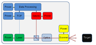
Figure 1. The simplified block diagram of a typical Imaging LIDAR system.
MATHEMATICAL FORMULATION
Figure 1 shows a simplified block diagram of a typical Imaging LIDAR setup. The system consists of a laser source, an optical system and a detector. Every sub-system includes a power supply, and its necessary electronics. A scanning system might be used, in order to illuminate a larger surface, depending on the detector’s design and/or the laser optical power. The requirements for the development of an Imaging LIDAR system for the orbital rendezvous and docking, the soft landing and rover operation in the context of the upcoming Exploration missions like the Mars Sample Return this report, the surface is always assumed to be within a range gate. Background photons can arrive at any time within the range gate across the full FOV, whereas the signal photons will only backscatter off the target.
THE DEVELOPED SIMULATION GUI
The primary purpose of the LIDAR performance model is to determine the performance of the LIDAR instrument. This allows the design to be optimized in terms of identifying the major sub-system level parameters that influence the instrument performance. The model calculates both the signal and background flux rate in photons observed by the instrument. Apart of the LIDAR instrument setup, the target size and environmental parameters have to be taken into account. The current version of the IL performance model is shown in Figure 2. It consists of five main panels, including the input instrumental and environmental parameters, and the necessary 2D, 3D and quality plots for visual inspection of the results. Statistics of image recovery is also provided.
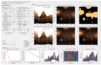
Figure 2. The layout of the Imaging LIDAR Simulator performance model. Input parameters are inserted in the top-left panels, while the input and output 2D and 3D images are created on the top-right. Quality plots and data exporting information are available on the bottom of the interface.
]]> METHODOLOGYOnce the target surface and its reflecting properties are inserted into the model, the ideal image is produced representing the “perfect LIDAR return”, with resolution given by the user, referring to the final detector format (detector array or single-element scanned array). For the sake of uniformity, the detector array is assumed to be square, with uniform properties across all its pixels (similar QE, FF etc). The signal and background photon arrival rates are then computed from the input instrument parameters. The probability of observing a signal photon or a background photon can then be computed. The ground is then located within the range gate. A background and a signal image are then constructed with the range value of all returned photons. These two images are combined and the raw LIDAR image is constructed (Figure 3). This image can be post-processed using a smoothing algorithms and special filtering.
SIMULATIONS – EXPERIMENTAL TESTS
It is observed that the boundary temperature variations affect drastically the outgoing laser beam shape, resulting in an unfocused and highly divergent non-Gaussian beam. Recent experimental tests demonstrated that small environmental temperature changes as small as 1° C can drastically affect the performance of the PU. This is a result of multiple physical factors being affected simultaneously from temperature (such as the LD’s wavelength of operation, the LD’s optical to optical efficiency, the absorption profile of the Nd:YAG crystal, the crystal boundary temp. conditions, ASE etc.). Our simulations can resample the existing experimental results and can predict the laser beam profile as a function of the boundary conditions, giving accurate quality results (Figure 5). Moreover, additional results have to be collected for the algorithm calibration. This will be done by in-situ experimental tests performed on a Nd:YAG crystal slab and its amplification performance as a function of temperature perturbations. These final results will provide the actual images required for accurate calibration of our algorithms.
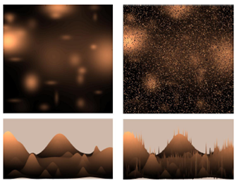
Figure 3. An example of input and output from the Imaging LIDAR performance model. An artificial surface is inserted in the simulator, as a 2D matrix or a 3D map, as shown on the two left panels. The panels on the right show the output 2D and 3D color indexed maps, of the same surface, as seen from a LIDAR device, using a certain set of parameters.
CONCLUSIONS
Experimental The developed Imaging LIDAR Simulation model designed especially to test the performance of the Imaging LIDAR can be used as a virtual LIDAR device, where the user will be able to test potential novel technologies in the frame of imaging and ranging devices. These results will support the future Imaging LIDAR technology developments by providing key information on sub-system level design parameters and there impact on the system performance. It gives a variety of input parameters and their combinations, where one can choose a wide variety of parameters, applications, target specifications and be as flexible as possible, covering all major LIDAR applications and working environments. The output 2D and 3D plots allow a visual inspection of the LIDAR return image, while the quality plots and statistical information quantify the results. Postprocessing may be applied to the final LIDAR return image, in order to improve the quality of the image and increase the overall restoration. Optimization of the model is practically unlimited. The GUI can always be updated in the future versions may come out in the future. Some of the future modifications and possible updates may include a fully controlled detailed target surface, create custom surface or input a 3D map from available archival data (or software produced, i.e. PANGU). The output of the IL Simulation Model can be used as the input for other applications, while the output of other applications can be used as an input of the current software. This will create a functional model, flexible enough to work in cooperation with other commercially available software and hardware products.
]]>