


Servicios Personalizados
Revista
Articulo
 Inglés (pdf)
 Articulo en XML
 Referencias del artículo
 Enviar articulo por email
Indicadores
-
 Citado por SciELO
 -
 Accesos
Links relacionados
-
 Similares en
SciELO
Similares en
SciELO
Compartir

 Permalink
Revista de Medio Ambiente y Mineria
versión impresa ISSN 2519-5352
REV. MAMYM vol.7 no.2 Oruro dic. 2022
ARTÍCULOS ORIGINALES
Applying a flexible model for analysis of stress-strain problem in room and pillar mining
Navarro-Torres, Vidal Félix1
1 Vale Institute of Technology (ITV). Ouro Preto - MG - Brasil, (vidal.torres@itv.org)
Abstract
In room and pillar (R&P) mining, the procedures adopted to design mine panels are based on the safety factor (SF) of pillars. For this reason, is so important to study the geological and geomechanical behavior of the areato be mined. The use of a mathematical model allows identifying problematic áreas and to test different configurations in a safe manner. This paper shows the development and application of a flexible and automatic routine to quantify the safety in R&P mining in terms of SF and room convergence (RC). The commercial software package FLAC3D was used to implement a computational routine in FISH language capable of representing in a fast and accurate way the main characteristics of the geomechanical conditions, lithology and geometrical features of a R&P mining project automatically. In order to show the capabilities of the routine developed here, a case of study was performed in a manganese ore mine.
Keywords: mining, room, pillar, numerical model, ore, recovery.
Resumen
En la minería de cámaras y pilares (R&P), los procedimientos adoptados para diseñar los paneles de la mina se basan en el factor de seguridad (SF) de los pilares. Por ello, es tan importante estudiar el comportamiento geológico y geomecánico de la zona que se va a minar. El uso de un modelo matemático permite identificar las zonas problemáticas y probar diferentes configuraciones de forma segura. Este trabajo muestra el desarrollo y la aplicación de una rutina flexible y automática para cuantificar la seguridad en la minería R&P en términos de SF y de convergencia de salas (RC). Se utilizó el paquete de software comercial FLAC3D para implementar una rutina computacional en lenguaje FISH capaz de representar de forma rápida y precisa las principales características de las condiciones geomecánicas, la litología y las características geométricas de un proyecto de minería R&P de forma automática. Para mostrar las capacidades de la rutina aquí desarrollada, se realizó un caso de estudio en una mina de mineral de manganeso.
Palabras clave: minería, sala, pilar, modelo numérico, mineral, recuperación.
1. Introduction
Room-and-pillar (R&P) mining is a mining method whereby the material of a series of crossing rooms (horizontal linear openings) is extracted, leaving pillars of ore, rock, or coal in place between the rooms. In hard rock masses, pillars are usually much smaller horizontally than rooms. According to Idris et al. (2015) a pillar can be defined as the in-situ rock mass between two or more underground openings. Pillars can be composed only by ore, or by ore and waste when the ore body presents small thickness. In some cases, this type of mining may need the use of ground support systems such as cable bolting or any other.
Because of underground openings are supported by pillars containing ore, it is very important to define a pillar with the smallest cross-sectional área possible and compatible with the room's stability, considering the traffic of mining equipment. This optimum configuration allows increasing the ore recovery. However, the optimum size of pillars (which guarantee stable rooms) depends on the active load on the pillar and also on its strength. The evaluation procedure of the stability of the pillars and rooms should be carried out by the estimation of the SF. Traditional strength-based pillar design requires estimates of pillar stress and pillar strength. The safety factor for the pillar is then calculated dividing pillar strength by the acting pillar stress. The definition of what constitutes an acceptable SF depends on the tolerable risk against failure (Bullock, 2011).
The method described above needs some simplifying assumptions such as stress averaging over the section of the pillar or arbitrary strain reductions (Idris et al. 2015). The use of numerical methods can helps us to avoid these simplifications in an efficient way using, for example, the strength reduction method SRM. The SRM uses a proportional reduction of the strength parameters up to reaching a limit equilibrium condition. This method is implemented in its three-dimensional versión in commercial software packages such as FLAC3D (Itasca Consulting Group Inc., 2012), among others.
On the other hand, the safety of rooms can be evaluated using a convergence limit approach given that a failure event is commonly characterized by a specific target limit valué (absolute or relative) of the sum of the inwards displacements of the roof and the floor. The room convergence (roof-floor convergence) can be measured at its critical position, i.e. located in the intersection of the two orthogonal rooms for regular geometries.
Both features described above, i.e. safety factor and room convergence, can be obtained from a flexible numerical model automatically to serve as input parameter for further decisión analyses. Thus, this paper describes the implementation of the flexible model built using the commercial software package FLAC3D (Itasca Consulting Group Inc., 2012) as well as its application to a real case study in a manganese ore mine.
2. Numerical modelling
According to Coulthard (1999), numerical modelling can assist the geotechnical engineer in designing underground excavations and support systems. If extensive geological and geotechnical data are available, then comprehensive predictions of deformations, stability and support loads can be made by numerical stress analyses. If not, the model can still be used to perform parametric studies, providing insight into the possible range of responses of a system, given the likely ranges for the various parameters
Brandani (2011) cites the main objectives of numerical methods regarding to pillar's design as:
Obtaining an estímate of load capacity or máximum permissible load;
Geometric configuration appropriate to the estimated stress field;
Determination ofmodes of rupture;
Retro-analysis of rock mass properties based on instrumentation data.
2.1. Constitutive model description
In computational modelling, two constitutive models are commonly used: Mohr-Coulomb (MC) and generalized Hoek-Brown (HB) with elasto-plástic behavior (Navarro Torres, 2003). Relating the failure criteria, the Mohr-Coulomb criterion can be expressed as a function of the axial (major) principal stress ct'i for different valúes of confining (minor) stress σ 3, according to Equation 1, which includes the rock mass strength and the k factor:
![]()
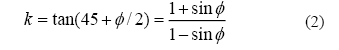
where k is the slope factor and σcm the uniaxial compressive strength UCS of the rock mass. The k factor is the slope of the line obtained when representing σ 1 as a function of σ 3 and it depends on the friction angle φ of the rock mass:
The uniaxial compressive strength σcm of the rock mass is calculated using Equation 3, as function of cohesión C and friction angle Φ:
![]()
Hoek e Brown (1980) aimed to represent the failure of rock masses through an empirical criterion in terms of major and minor principal stresses. The original Hoek-Brown criterion was defined by the following equation:
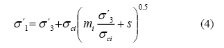
where σ1 and σ3 are the major and minor effective principal stresses at failure; σci the UCS of the intact rock; and, m and s are material constants which depend on rock properties. For intact rock, s = 1. When there is no lateral confinement (σ3= 0) and s = 1 (laboratory), the uniaxial tensile strength of the rock or rock mass is determined considering σ1 = 0, and σ3= σ1 resulting the follow equation:
![]()
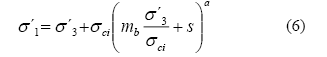
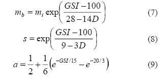
Later, Hoek et al. (2002) presented the Generalized Hoek-Brown criterion which includes not only results from laboratory but valúes observed from observed failures in fractured rock masses in a non-linear manner. This non-linear criterion can be described according to Eq.
The deformability of the rock mass was estimated using the Hoek and Diederichs (2006) formulation:
![]()
where Ei is the modulus of deformability of the intact rock estimated as:
![]()
where MR is the modulus reduction factor
2.2 Modeling routine
The great amount of information necessary to build a robust numerical model along with the necessity of evaluating diverse mining situation made necessary the development of a flexible tool capable of represent this generality. Therefore, a flexible and robust routine was written in FLAC3D, using FISH language, aiming to perform safety analyses of room and pillar mining automatically. FLAC3D was chosen because of its 'driven-command' functionality, which turns it very flexible intrinsically.
The routine considers that all layers are horizontal of constant thickness and that pillars are regularly distributed in a horizontal section. Pillars were considered to be rectangular shaped and rooms of equidimensional and orthogonally positioned.
The entire lithology and rock mass mechanical properties are read from a text file and the model is built above, below and at the mining level considering depth, thickness and material properties. Rock mass strength can be described using either MC or HB constitutive models. Some geometrical details of the model such as approximate zone target sizes can be specified. In addition, the excavation process can be considered by an instantaneous deletion process or by a progressive core softening process.
The main output of the model is constituted by the safety factor SF and the room convergence RC. Naturally, all the mechanical state variables can also be explored and analyzed using the FLAC3D graphical/command capabilities. The safety factor reported correspond to that obtained by the use of the Strength Reduction Method (Dawson et al. 1999) in FLAC3D. On the other hand, room convergence is measured at the intersection of two perpendicular rooms. Despite the routine is capable of modeling any rectangular number of pillars (number of pillars along x-axis time the number of pillars long y-axis), the symmetry of the conceptual model enable the use of only one pillar to represent an entire mining complex of similar characteristics. Non-symmetric conditions were not contemplated in this routine and they need to be studied in detail in a particular numerical model.
3. Case study
The case study presented here exhibits part of the mining plan of a pilot área of a manganese ore mine located at Brazil. The pilot área, objective of this study, is composed of nine pillars. Linear rooms of 5 m width were excavated perpendicularly, conditioning the formation of approximately 15m x 15m pillars. These dimensions represent an ore recovery of 44%, leaving a remaining ore amount of 56% of the available quantity, thus, generating an interest in increasing the recovered amount in a safe way. Therefore, the main objective of this study is to evalúate the safety of the R&P mining at the current configuration in order to judge if further exploration is feasible.
The capabilities of the flexible routine presented here were explored through the evaluations of the stability conditions of the current configuration of the mine as a function of the rock mass strength.
In order to consider the geomechanical quality of the several layers inthe numerical model it was necessary to elabórate a significant classification. These data are based on the lithologic sequence of the adjacent rocks (hanging wall and footwall) of the manganese ore layer. 3.1. Numerical modelling and simulation
The numerical model of the case study mine was built in FLAC3D considering 44 lithologies, alternating 4 rock types above the mining level (approx. 150 m cover) and a homogeneous rock with 50 m thick below the mining level (Figure 1). The constitutive model used was the Mohr-Coulomb and the mining process was considered instantaneous.
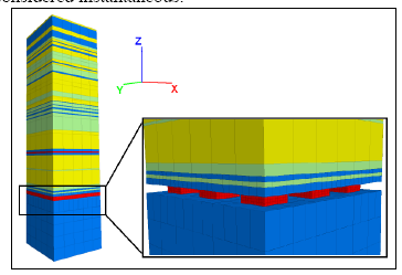
Figure 1. Lithology of the numerical model of 9 pillars with detail in the manganese layer.
4. Results and discussion
4.1. Model calibration
By knowing the conditions of the depth of the current mining panel of the manganese layer, the lithology above the target level, quality of blasting with explosives (D = 0.8) and intact rock strength; the resistance parameters to be used in the numerical model may be estimated based on the formulation shown by Hoeketal. (2002).
The parameters of the layer obtained through the above formulation are presented in Table 1. The variability present in the input data conditions an uncertainty propagation in the geomechanical parameters of the numerical model. Given that UCS of the intact rock presented the main variability, a sensitivity analysis of this parameter is necessary. Therefore, the response variation was studied as a function of the UCS of the intact rock.
Table 1. Geomechanical parameters of the manganese mineral rock mass
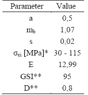
*Disperse laboratory results ranging from 30 to 115 MPa
** Judgement of specialist - Navarro-Torres V.F.
The variability of UCS of intact rock impose a dispersión in the Mohr-Coulomb parameters. In fact, there exist a co-dependency as shown in Figure 2. It can be observed that the rock mass cohesión varíes between 5 and 21 MPa in an approximately linear fashion and that the friction angle varíes non-linearly from 34.5 degrees to 36.3 degrees approximately.
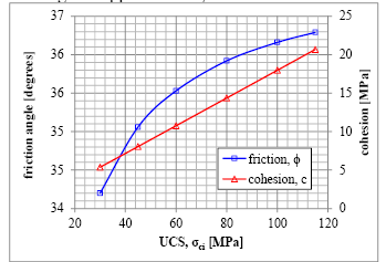
Figure 2. Mohr-Coulomb parameters dependency with UCS of the intact rock
In addition, the variability in the UCS of the intact rock imposes a dispersión on the modulus of deformability Erm. The dependency relation between UCS and Erm is shown in Figure 3.
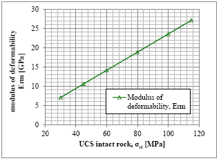
Figure 3. Dependency of UCS and Erm for the studied manganese rock mass.
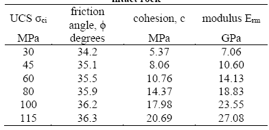
A discrete variation of the parameters described above is presented in Table 2.
Table 2. Dependency of the friction angle, cohesión and modulus of deformability with respect to UCS of the intact rock
4.2. Safety evaluation of the current condition of the mine
The representations the rock mass state are discretized in three strength resistance levéis: minimum - 30 MPa, médium - 60 MPa and máximum - 115 MPa. Stress-strain runs of the current geometrical configuration studied here presented vertical stresses at the section of the pillar varying from 8 to 15 MPa and máximum vertical downwards displacement of the roof ranging from 5 to 10 mm, as show in Figure 4.
Additionally, the floor exhibited small máximum vertical upwards displacement of the order of 5 mm. In all cases, it was observed that stress distributions were similar as well as the displacements for the three studied scenarios. This behavior suggests that the material of the pillars is working mostly elastically and far from a generalized plastification in all analyzed resistance states, i.e., the integrity of the pillars presents a considerable safety margin.
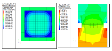
Figure 4. Vertical stress and vertical displacement. 15xl5m pillar, minimum resistance.
Complete safety analyses (stress-strain plus SRM calculation) yielded results relative to the safety factor and the room convergence of the current state of the mine. Table 3 presents the safety factor and the room convergence according to the UCS of the intact rock. In addition, Figure 5 shows the same information in a graphical manner. It can be seen that FS rises from 3.7 to 9.3 following a linear tendency. On the other hand, room convergence decreases non-linearly from 18 mm to 14 mm.
Table 3. Discrete dependency of friction angle and cohesión respect to ÜCS of intact rock.
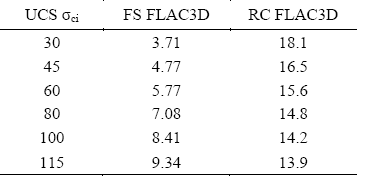
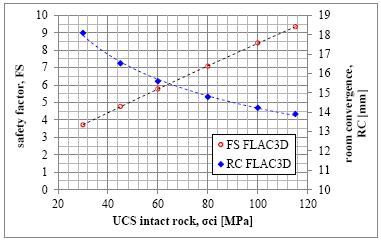
Figure 5. Variation of FS and RC according to the strength of the intact rock.
The method used for assessing the safety factor was the strength reduction method (automatic), where the valúes obtained for SF can be considered compatible with empirical formulations (Navarro Torres et al., 2011). The variability of the safety factors obtained from the simulations of this case study for a material strength UCS ocl which varíes between 30 to 115 MPa, with a slimness ratio of 0.23, resulted in a safety factor varying from 3.71 to 9.34 which can be considered as highly safe given that the minimum required is 1.5.
Room convergence presented valúes ranging from 18 to 14 mm representing non-dimensional convergence of 0.5% to 0.4%. These valúes can be considered inside a satisfactory roof behavior owing that some minor problems might begin to appear from 1% ahead according to practice standards (Solak, 2009; Hoek and Marinos, 2000; Singh and Goel, 1999; Tonon, 2012; Ósterreichische Gesellschaft für Geomechanik, 2001; Schubert; Goricki and Riedmuller, 2003).
The model developed showed satisfactory and promising results but still needs to be improved/calibrated with data to be obtained from the analysis of rock samples and instrumentation that are in progress to better understand the current property valúes of the material involved in the model. After a more refined knowledge of the model material parameters, this new model might be used for an optimization process of the ore recovery.
5. Conclusions
A three dimensional numerical model was developed and presented in this paper with innovative characteristics, which includes an excellent flexibility and geomechanical and geometrical adaptability to different scenarios, according to the variability of operational and geomechanical conditions of the manganese ore mine. The methodology shown along this paper can incorpórate important features of the rock mass as lithology and behavior of rocks. It can be applied to a single pillar as well as to an unlimited number of pillars allowing the simulation of large áreas of mining panels and application to various scenarios. The current available data leads to judge the mining pilot área as highly safe given that the factor of safety was found to lie between 3.7 and 9.3 being that the minimum required is usually higher than 1.5. In addition, the room convergence presented valúes smaller than 18 mm representing a stable behavior according to literature. Finally, the use of new information coming from laboratory and in situ instrumentation will allow us to calibrate the model and henee to reduce the variability in the response evaluated generating a higher reliability upon the results and future applications.
Acknowledgments
To the work of researchers of Vale Institute of Technology (ITV) and Vale.
References
1. Brandani, D. B. (2011) Estudo do comportamento geomecánico de pilares esbeltos modelados em rocha dura na bacia do Corpo I, Mina Nova - Crixás/GO. Dissertation. Federal University of Ouro Preto - UFOP. 187 p. [ Links ]
2. Bullock, R. L. (2011) Room-and-Pillar mining in hard rock. In: Peter, Darling, 3rd edition. Society for Mining, Metallurgy and Exploration (U.S.). Mining Engineering Handbook. (pp. 1327-1338) [ Links ]
3. Coulthard, M. A. (1999) Applications of numerical modelling in underground mining and construction. Geotechnical and Geological Engineering 17: 373-385. [ Links ]
4. Dawson E, Roth W, Drescher A. Slope stability analysis by strength reduction. Geotechnique. 1999;49(6):835-840 [ Links ]
5. Hoek, E., Carranza Torres, E. and Corkum, B. (2002) Hoek-Brown Failure Criterium - 2002 ed. In: Proceedings of the 5th North American Rock Mechanics Symposium and 17th Tunnelling Association of Canadá Conference: NARMS-TAC 2002, July 7- 10, University of Toronto. (pp. 267-271) [ Links ]
6. Hoek, E and Diederichs, M.S. (2006) Empirical estimation of rock mass modulus. International Journal of Rock Mechanics and Mining Sciences, 43, 203-215. [ Links ]
7. Hoek, Evert, and Paul Marinos. (2000) Predicting tunnel squeezing problems in weak heterogeneous rock masses. Tunnels and tunnelling international 32.11 : 45-51. [ Links ]
8. Idris, M. A., Saiang, D., Nordlung, E. (2015) Stochastic assessment of pillar stability at Laisvall mine using Artificial Neural Network. Tunnelling and Underground Space Technology, V49 (pp. 307-319) [ Links ]
9. Itasca Consulting Group, Inc. (2005) FLAC3D -Manual of Fast Lagrangian Analysis of Continua in 3 D. Constitutive Models: Theory and Implementation (pp. 2-1/2-92) [ Links ]
10. Itasca Consulting Group, Inc. (2012) FLAC3D -Fast Lagrangian Analysis of Continua in 3 Dimensions, Ver. 5.01. Minneapolis: Itasca. [ Links ]
11. Navarro Torres, V. F. (2003) Engenharia Ambiental Subterránea e Aplicacóes a minas Portuguesas e Peruanas. Tese de Doutorado Instituto Superior Técnico da Universidade de Lisboa, 585 p. [ Links ]
12. Navarro Torres, V. F., Da Gama, C, Silva, M. C, Falcao, P. and Xie, Q. (2011) Comparative stability analyses of traditional and selective room-and-pillar mining techniques for sub-horizontal tungsten veins. International Journal of Minerals, Metallurgy and Materials Volume 18, Number 1. (pp. 1-8) [ Links ]
13. Ósterreichische Gesellschaft für Geomechanik. (2001). Richtlinie für Geomechanische Planung von Untertagebauarbeiten mit Zyklischem Vortrieb, Salzburg. [ Links ]
14. Schubert, W., A. Goricki, and G. Riedmuller. (2003). The guideline for the geomechanical design of underground structures with conventional excavation. Felsbau 21.4 : 13-18. [ Links ]
15. Singh, Bhawani, and Rajnish K. Goel. (1999). Rock mass classification: a practical approach in civil engineering. Vol. 46. Elsevier. [ Links ]
16. Solak, T. (2009). Ground behavior evaluation for tunnels in blocky rock masses. TUST 24. 323-330. [ Links ]
17. Tonon, Fulvio. (2012). Tunneling in Difficult Conditions-The Squeezing Case. Geotechnical Engineering State of the Art and Practice: Keynote Lectures from GeoCongress 2012. 380-397. [ Links ]
Artículo recibido: 26.10.2022
Artículo aceptado: 18.10.2022

