


Servicios Personalizados
Revista

Articulo
 Español (pdf)
 Articulo en XML
 Referencias del artículo
 Enviar articulo por email
Indicadores
 Citado por SciELO
 Links relacionados
 Similares en
SciELO
Similares en
SciELO Compartir

 Permalink
Revista de Medio Ambiente y Mineria
versión impresa ISSN 2519-5352
REV. MAMYM no.5 Oruro 2018
ARTÍCULOS
Radio Frequency Identification (RFID) technology applied in underground mining
Tecnología de Identificación por Radio Frecuencia (RFID) aplicada en minería subterránea
Juan Pablo Ferreira Centeno a, Vidal Félix Navarro Torres b & Leandro Silveira c
a Secretaría de Minería de Córdoba, Córdoba, Argentina, jp.ferreiracenteno@gmail.com
b Vale Institute of Technology, Belo Horizonte, Minas Gerais, Brazil,vidal.torres@itv.org
c Vale Institute of Technology, Belo Horizonte, Minas Gerais, Brazil, Leandro.silveira@itv.org
Abstract
The developments of applied RFID technology overcome all supposedly insurmountable obstacles and limits because it allows monitoring everything that moves in the mine. These features make it possible to apply such technology for the comprehensive safety plan of the underground mine. For instance, this research paper presents "online" RFID technology applied to a full safety system for underground mines exploited by any mining method. This technology allows the identification of each worker, their functions and localization in the mine. On the other hand, it is applicable to the identification of the underground mine equipment and their movement, thus permitting to control productivity and safety.
Keywords: Security, underground mine; RFID; identification; radio frequency.
Resumen
El desarrollo de la tecnología RFID aplicada supera todos los obstáculos y límites que son supuestamente insuperables, porque permite monitorear todo lo que se mueve en la mina. Esta particularidad hace posible aplicar tal tecnología para el plan de seguridad integral de la mina subterránea. En ese sentido este trabajo de investigación presenta la tecnología RFID "online" aplicada para un sistema de seguridad completo para minas subterráneas explotadas por cualquier método minero. Esta tecnología permite la identificación de cada uno de los trabajadores, de sus funciones y su localización en la mina. Por otro lado, es aplicable para la identificación de los equipos de la mina subterránea y su movimiento, permitiendo por lo tanto controlar la productividad y la seguridad.
Palabras clave: Seguridad; mina subterránea; RFID; identificación, radio frecuencia.
1 Introduction
The radio frequency identification (RFID) is the technology to automatically capture and identify information stored in electronic cards called tags, within the range of the RFID reader. This information stored in tags memory is transmitted by radio without physical or visual contact.
The principal feature of this identification system is to provide an important added value because the RFID chip can store a lot of information [1].
When the tags are linked to a RFID reader antenna range, this unit emits a signal to the tag in order to get the information of the card. Generally this information consists exclusively in an identification code (Fig. 1).
The keys of the technology are that the information recovery is carried out by radio frequency and no physical or visual contact is required. Nevertheless, in most cases the range of a reader is quite short so both elements of the RFID system, card and reader, must be close to each other.
The radio wave spectrum permits the use of a wide range of frequencies (Fig. 2), each one of them can be used to improve results, for instance increase the reading range, minimize distortions induced by high humidity media, reduce signal propagation errors in metallic ore bodies etc.
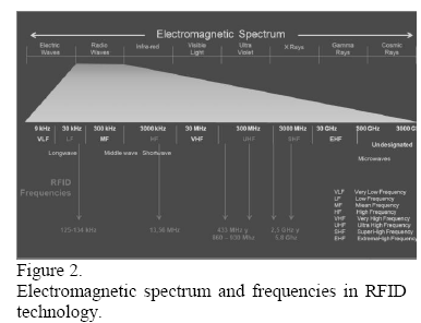
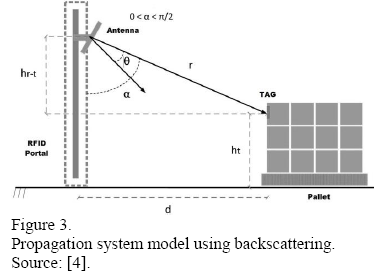
Fig. 3 shows schematically a RFID propagation system model using backscattering. It is possible to see the antenna and a lower level object with the TAG [1-3].
The eq. (1) [5] is used to calculate the loss expressed in decibels for this two ray models.
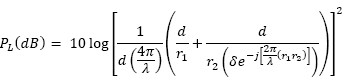
Where d is the distance between reader and TAG and λ is the wavelength of the signal. The δ parameter is related to wave polarization effects and, for a horizontally positioned antenna, is expressed by [6]:
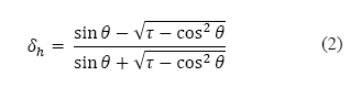
Same way it is possible to express the value of δ for a TAG antenna vertically positioned.
Where θ is the incidence angle, ht is the height of the reader antenna and hr is the TAG height.
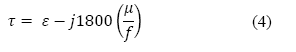
The parameter τ depends on the relative permissivity, ε, the reflector material conductivity, µ, and also on the operation frequency, f. It is expressed by eq. (4) [5].
Finally r1 and r2 are the length of the radio wave reflected routes; r1 is the distance between the transmission antenna and the reflection point and r2 is the one between the reflection point and the reception antenna. They are calculated by:

2 RFID Technology
2.1 Identification using RFID
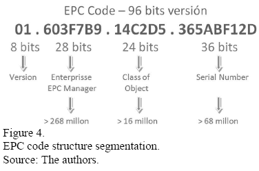
This technology followed the same way of the bar code. After heterogeneous beginnings follows the standardization in the form of EPC (Electronic Product Code). This code has a design structured based on 96 bits, segmented in 4 fields. (Heading, producer identification, product identification and serial identification) [2,7,8].
This quantity of digits allows a quite large number of combinations (Fig. 4).
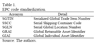
The standardization implies that it is necessary to define certain number of identification internal structures to satisfy different requirements (Table 1).
2.2 Components and electronic cards (TAG) types
This technology is classified as AutoID (Auto Identification). A RFID card is a small gadget that can be attached to an object, an animal or to persons clothes. Contains antennas to receive and answer requisitions by radiofrequency emitted from a RFID transmitter receiver.
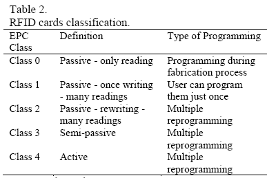
Taking into account the power supply, it is possible to classify cards into 3 types: passive, active and semi passive.
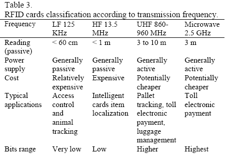
The cards can also be classified by the different kind of programming you can do, and the transmitting wave band (Tables 2-3).
2.3 Selecting a TAG
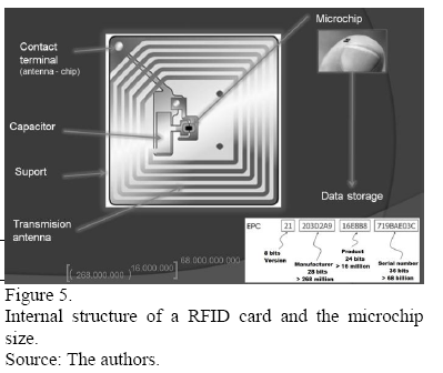
It is necessary to consider the storage capacity of a TAG. At the beginning the capacity was 64 bits. Nowadays the standard is 96 bits but is expectable the use of 128 or 256 bits cards in next years.
The internal tag structure is composed by microchip, antenna ship, capacitor, support, and transmission antenna. The antenna mounted on a base involves the capacitor for that provide power energy for data reading on the chip and these are transmitted as a radio signal and also show the size of the memory microchip (Fig. 5) [9].
Probably it would be necessary to use different cards for each point, equipment or people. Table 4 illustrates some particularities of active and passive TAGs [1,3,10].

For TAG selection the most important parameters to consider are as follows:
- TAG adhesion;
- Passive or active functioning;
- TAG reader range;
- Size and weight;
- Transmission velocity;
- Orientation sensibility;
- Kill/Disable (In habilitation);
- Write Once;
- Write Any;
- Anti-collision;
- Security and encryption;
- Supported standards.
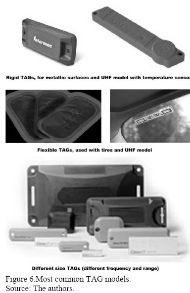
The most common TAGS are rigid and flexible (Fig. 6).
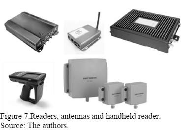
2.4 Readers and antennas
Readers call transceivers in electronic field and them act as identification station signal request transmitted to the TAGs and getting the answer to the requests. A reader needs one or more antennas to communicate with TAGs (Fig. 7).
Estes acts as station identification request signals transmitted to the TAGs and getting the answers to these requests.
The selection of the antennas is not a minor issue, depending on the location of the same sector should opt for the method of radiation from them. These methods are classified into isotropic radiation, omnidirectional and directive. In underground mines most people has selected the directive radiation type, using robust readers that permit the use in hostile environments (Fig. 8).
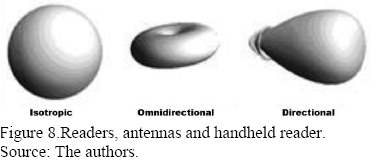
One of the most important features of the radiation standard is the hability to energy oriented, which provides more power in a reading direction. When gain increasing in such antenna, the radiation angle of the signal decreases. It must be balanced in this election coverage radius of the antenna and the maximum reading distance.
The most important feature of the directive radiation standard is the possibility to energy direct in diverse direction (Fig. 9) [1,8,11].

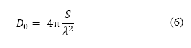
The directivity DO for this antenna calculates by eq. (6), where S is the area and λ is the wavelength.
2.5 Middleware
Readers works simultaneously and so are the readings of all over the objects using RFID cards within their range and this information must be transmitted to companies information systems. These facts lead to the essential use of an element that controls these readings.
This element is the middleware which is an informatics platform that permits to contextualize each one of cards and control them, using some criteria. This way, the TAG receipted signal is transmitted once and not hundreds of times from a same reading point. So the middleware administrates data and avoids collisions. This element permits to administrate the answering velocity that some events needs and associate those TAGs with an optimal emission frequency [3, 7].
In the middleware equipment selection, it is very important to consider the following conditions for de RFID platform:
- To control every type of RFID device;
- To capture data of the velocity and efficacy;
- To real time control TAG locations;
- To centrally control every internal or external RFID data sources;
- To secure data coherency;
- Send information to devices when necessary (Record a Chip).
- To permit wireless RFID net service.
- The goal of this service is to centralize every facility as security, data, telephony and video.
This wireless technology reduces costs and permits to accelerate the implementation of new underground sectors, also allowing to know the exact real time localization of all workers, equipment and device whose monitoring is necessary [3,7].
3 Possibilities of RFID technology application in underground mining
3.1 Supplies logistic distribution
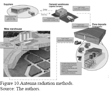
It is possible to incorporate the RFID technology in the logistics distribution network of underground mining operations in two different ways:
- Open circuit: the mining operation reuses the same TAG of the provider to track the products inside the mine (Fig. 10).
- Closed circuit: the mining company put new TAGs on the products that are going to be distributed in the mine environment.
In open circuit supplies logistics distribution, the supplies labeled by the provider are received at general warehouse and from this building they are going to be distributed to areal warehouses. Later on it is possible to further redistribute the labeled supplies to other surface or underground warehouses [8,9,10,12].
3.2 People localization in underground mine
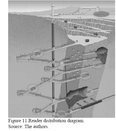
For mining safety, it is very important to know the exact location of each worker. At the same time it is also important to know exactly where the rescue and first aid teams are.
The main entrance as well as the level entrances must have strategically located readers to ensure the process. Generally the readers are located at the lifts doors. In Fig. 11 they are indicated by triangles.
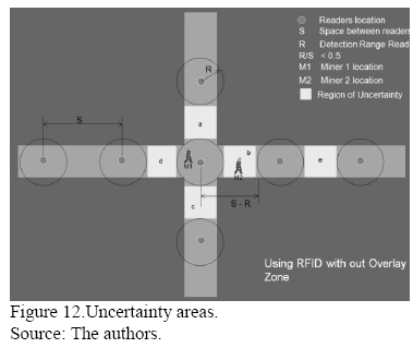
In drifts or ramps of underground mine the antennas are located based in the range and the spacing of readers. The goal is to decrease the personal location uncertainty areas. Fig. 12 shows a miner M1 detected using intersection drifts. If this worker moves in one the four possible directions nobody could say where he is until his TAG is read in other location provided with reader. So, in this case, considering the initial position of miner M1 there are four uncertainty zones: a, b, c and d.
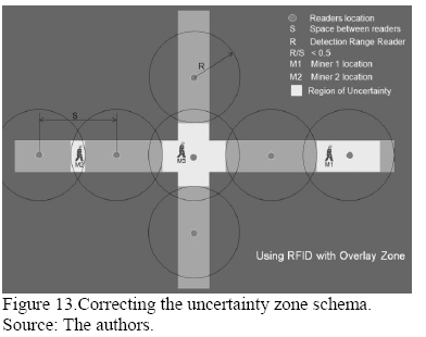
On the other hand Fig. 13 shows that changing the antenna position permits to reduce the uncertainty areas. So, it is not necessary to reduce the uncertainty areas to a near zero value. Structural ore body studies allow to determinate some low risk uncertainty zones.
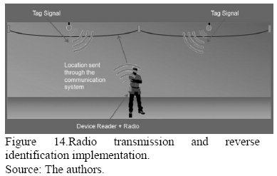
It is also possible to improve the accuracy of reader positioning by combining reverse identification process with radio transmissions. The method is very simple indeed. Active TAGs are installed along the drifts ceiling and this permits to increase the range and the spacing between them, providing the signal overlapping. In this case the miner carries the antenna, which includes a radio [13, 14].
There is a software in the device that calculates the distance to the active ceiling TAG doing 5 emissions per second and transmits the exact location through the communication system (Fig. 14).
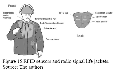
3.3 Evacuation and rescue ID and tracking
In underground mining accidents, it is essential to know the exact location of each worker and also to know where the rescue and first aid teams are. Thanks to the maps generated by software it is possible to immediately activate alarms and to implement evacuation protocols, to monitor and guide rescue teams, do the same with workers and conduct them to safe places or operating lifts, to stop truck traffic and to stop works affected directly or indirectly by the accident.
The members of rescue teams would wear last generation security jackets that use RFID TAG linked to a number of sensors and which also have external radio connection (Fig. 15).
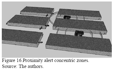
3.4 Detection areas
The proximity monitor warns the vehicle driver about workers and other equipment in his proximity. To do this, it is necessary to put a TAG and an antenna on the vehicle, which will work as a radar system, informing the driver to avoid collision or unsafe situations. The reader on the vehicle has a computer that warns about the proximity of people and equipment by emitting sound and light.
Boundaries of safety zones can be adjusted using algorithms that evaluate the intensity of the received signal, generating, for example a growing level sound (Fig. 16). Proximity monitor system requires a RFID wireless net and the suitable software. This software could use algorithms to adjust the range of detection zones, generally between 10 and 300 m.
The algorithm must provide the maximum security level and reliability and also consider the operator comfort. The system must have a non-invasive low level alert at the moment people or equipment come within a particular fixe range of alarm or restriction. The driver must have the possibility to disable the alert, but the incident must be registered in central safety system.
The combined Wi-Fi RFID applications have been tested in underground mining industry with success. One of the most remarkable are the Wi-Fi signals propagation around corners that generate virtual visibility environment on crossing galleries uncompromising the traffic there. In addition to this warning system on the vehicle, you can manage to posters LED for to display alerts and traffic regulates in underground environment. The precise location of the vehicle can be adjusted based on how the antennas are installed.
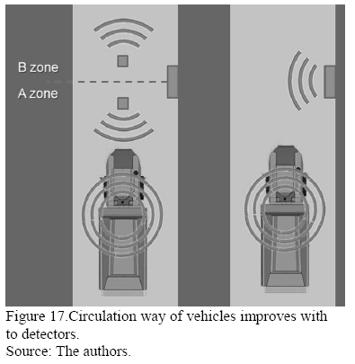
The system depicted in the right side of Fig. 17 has an antenna which can detect the moving equipment, but cannot identify its movement direction. The left side of the same figure shows that a system consisting of two ceiling detectors can provide enough data to process this information, allowing to determine the direction of the movement [3,7,10,13,14].
3.5 Exclusion areas
The exclusion zone subsystem can function as an autonomous component or totally integrated to the central safety system. The same system can be adapted to reduce the risk to workers who have no authorization to be near certain equipment (Fig. 18) [14].
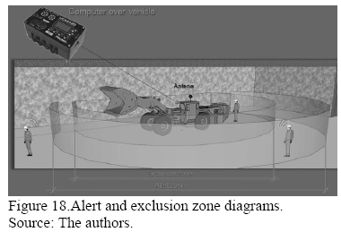
Different kind of sounds can identify people within alert or exclusion zones, and simultaneously recognize the arrival of additional equipment.
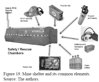
3.6 Underground safety rescue chambers
It is not necessary to inspect a mine safety shelter if all the standard elements inside have a TAG.
An antenna in the shelter permits to read the identification cards and to verify not only the existence of those elements, but also their condition (Fig. 19).
With the knowledge of the safety and survival elements contained in the shelter, it is possible to know how much people can be there and for how much time.
3.7 Integral safety system in underground mining
A system like this must be constituted by different subsystems:
- Supplies acquisition and distribution;
- Personal registry and tracking;
- Security: must include operational restricted areas, shelter locations etc;
- Equipment registry and tracking: must include equipment particular restriction areas, nearby authorized personal etc;
- Equipment collision control: includes the restricted area administration module;
- Equipment maintenance;
- Transport and traffic regulation: includes the traffic lights and LED signal module;
- Assignment and monitoring rescue team;
- Communication and VOIP telephony;
- Video.
Implementing and adapt every subsystem requires a multidisciplinary team that at least must be integrated by: mining engineers, geologists, logistic engineers, safety and rescue experts, informatics, communication engineers, accountants and lawyers.
Fig. 20 shows schematically the monitoring and the tracking possibility of workers, equipment, shelters etc., and their impact on the routine of underground mining [15].
This multidisciplinary challenge, should become a research project consortium to define minimum safety standards in underground environment using RFID.
4 Conclusions
The RFIDS technology applies in underground mines is very innovative and have great potential to contribute for safety problems solutions.
It is possible to develop such kind of project with norms and protocols of extreme safety standards using the technology presented here.
The cost of RFID elements is lower.
The RFID technology will be contribute to proactive and in real time operational and safety management in underground mining.
Acknowledgements
The authors would like to thank CYTED for financial support to the Underground Environment and Sustainability of Underground Environment Program and to the Sustainability Ibero-American Research Network. They are also grateful to Vale Institute of Technology – Mining for its institutional support.
References
[1] Glover, B & Bhatt,H. RFID essentials, Sebastopol, CA, USA, O'Reilly, 2006.
[2] Qiao, Y., Chen, S. & Tao, L. RFID as an infrastructure, New York, NY, USA, Springer, 2013.
[3] Thornton, F., Haines, B., Das, A., Bhargava, H., Campbell, A. & Kleinschmidt, J. RFID security, Rockland, MA, USA, Syngress, 2006.
[4] Goes, A. A. Modelo de propagacao empírico para sistemas RFID passivo. PhD Dissertation, Faculdade de Engenharia Elétrica e Computacao, Universidade Estadual de Campinas, Campinas, SP, Brasil, 2014.
[5] Siwiak, K. & Bahreini, Y. Radiowave propagation and antennas for personal communications, Norwood, MA, USA, Artech House, 2007.
[6] Saunders, S. & Zavala, A. Antennas and propagation for wireless communication systems, Chichester, England, John Wiley & Sons, 2007.
[7] RFID World Canada. Innovative UHF Gen 2 RFID reader/writer [online], 2010. [date of reference June 2nd of 2015]. Available at: < http://www.rfidworld.ca/innovative-uhf-gen-2-rfid-readerwriter/50
[8] Hunt, V., Puglia, A. & Puglia, M. RFID: a guide to radio frequency identification, Hoboken, NJ, USA, Wiley-InterScience, 2007.
[9] RFID World Canada. Long-range active RFID interrogator handles many tags simultaneously [online], 2011. [date of reference June 2nd of 2015]. Available at: http://www.rfidworld.ca/long-range-active-rfid-interrogator-handles-many-tags-simultaneously/562
[10] Atilano, R. H. Identificación de vehículos empleando RFID-EPC, Saarbrücken, Alemania, OmniScriptum / Editorial Académica Española, 2012.
[11] Ripoll, J. V. H. Diseño de antenas UHF para aplicaciones RFID, Engineering Thesis, Barcelona, España, Escola Técnica Superior d'Enginyeria, Universitat Autònoma de Barcelona, 2009.
[12] RFID World Canada. New RFID solution decreases maintenance times on Boeing airplanes [online], 2011. [date of reference June 2nd of 2015]. Available at: http://www.rfidworld.ca/new-rfid-solution-decreases-maintenance-times-on-boeing-airplanes/249
[13] Mine Safety and Health Administration (MSHA) – www.msha.gov
[14] National Institute for Occupational Safety and Health (NIOSH) – www.cdc.gov/NIOSH/
[15] Navarro Torres, V. F., Dinis da Gama, C. & Villas Boas, R., Engenharia ambiental subterránea e aplicaccoes, Rio de Janeiro: CETEM / CNPq / CYTED, 2005.

