


Servicios Personalizados
Revista
Articulo
 Inglés (pdf)
 Articulo en XML
 Referencias del artículo
 Enviar articulo por email
Indicadores
-
 Citado por SciELO
 -
 Accesos
Links relacionados
-
 Similares en
SciELO
Similares en
SciELO
Compartir

 Permalink
Investigación & Desarrollo
versión impresa ISSN 1814-6333versión On-line ISSN 2518-4431
Inv. y Des. vol.18 no.1 Cochabamba 2018
http://dx.doi.org/10.23881/idupbo.018.1-7i
ARTÍCULOS – INGENIERÍAS
SHAFT ALIGNMENT MEASUREMENT SYSTEM DEVELOPED FOR INDUSTRIAL APPLICATIONS
DESARROLLO DE UN SISTEMA DE MEDICIÓN DE ALINEACIÓN DE EJES PARA APLICACIONES INDUSTRIALES
Iván Mendoza and Grover Zurita
Laboratorio de Innovación Tecnológica Industrial y Robótica (LITIR)
Universidad Privada Boliviana
Cochabamba-Bolivia
(Recibido el 5 de Mayo 2018, aceptado para publicación el 25 de Junio 2018)
ABSTRACT
In the industry, the shaft misalignment is considered a common fault in rotating machines. Inadequate alignment of rotating shafts through couplings often lead to severe vibration complications with premature failure of machines parts. It is, without uncertainty, the greatest loss of profits allocated to misalignment, resulting limited production, increasing energy cost, increasing downtime and premature breakdown of the equipment. It´s of a big paramount to optimize the rotating machines efficiency by an appropriate alignment technique. Therefore, from aforementioned, the main objective of this research work is to develop a low-cost, with high precision shaft alignment measurement system for industrial applications. The developed prototype was based on an inductive sensor system, which is a non-contacting and electronic dial indicator equipment. It was used an Arduino Uno for the data acquisition procedure and Matlab® for the data analysis processes. The performance and the effectiveness of the proposed measurement system were verified by an experimental validation procedure. Finally, the research approach was successfully accomplished, by developing a shaft alignment system with ultra-low cost with high degree of accuracy. The overall average standard deviation of the experimental data set was about 0.02 mm, which is under the standard recommended values for alignment.
Keywords: Misalignment, Induction Sensor, Rotating Machinery, Condition Based Maintenance (CBM).
RESUMEN
En la industria, se considera una falla común en las máquinas rotatorias la desalineación de ejes. La inadecuada alineación de los ejes giratorios a través de acoplamientos a menudo conduce a graves complicaciones de vibraciones, con falla prematura de las piezas de las máquinas. Es sin duda alguna, la mayor pérdida de ganancias asignada a la desalineación, resulta en una producción limitada de los equipos, aumento del costo de la energía, aumento del tiempo de inactividad y la falla prematura de equipos. Es muy importante optimizar el rendimiento de las máquinas rotativas mediante la alineación adecuada. Por tanto, el objetivo principal de este trabajo de investigación es desarrollar un sistema de medición de alineación de ejes de alta precisión y de bajo costo para aplicaciones industriales. El prototipo desarrollado se basó en un sistema de sensor inductivo, que es un equipo sin contacto y con indicador electrónico. Se utilizó un Arduino Uno para el procedimiento de adquisición de datos y Matlab® para el proceso de análisis. El rendimiento y la efectividad del sistema desarrollado, se verificaron mediante procedimientos experimentales. Finalmente, se logró con éxito el desarrollo de un sistema de alineación de ejes de bajo costo, y con un alto grado de precisión. La desviación estándar promedio global del conjunto de datos experimentales fue de 0.02 mm, el cual está por debajo de los valores estándar recomendados para la alineación de ejes industriales.
Palabras Clave: Desalineación, Sensor de Inducción, Maquinaria Rotativa, Mantenimiento Basado en la Condición (CBM).
1. INTRODUCTION
The companys strong competitiveness for effectiveness, have forces to reduce production costs and maintain the availability of production equipment. In the recent years, to reduce downtime and maintenance cost, Condition Based Maintenance (CBM) method was used. In order to reduce the uncertainty of maintenance activities and recommends maintenance actions based on the information collected through condition monitoring [1]. The CBM tries to avoid unnecessary maintenance tasks by taking on tasks only when there is evidence of abnormal equipment behavior. Some of the advantages of the CBM include prior notice of the impending failure and greater accuracy in the prediction of the failure. The preventive industrial maintenance activities seek to optimize the useful life of all the components of a system (motors, gear, fans, flywheels, rolling bearings, shafts, and couplings), taking care of the optimal operation of the same with the components operating in confidence ranges.
The shaft and couplings, are responsible for transmitting the work done by a generating source (driven motor) to a driven equipment, these couplings act as links between two machines keeping the axes of both centered machines [2]. If the couplings do not keep the axes centered, premature failure of the same couplings and bearings occurs. The cause of this failure is known as misalignment, where the axes of the rotating machines are not kept centered. To carry out the alignment severity level of in rotating machines, the preventive/predictive maintenance is necessary to monitor the equipment operation, to prevent machine failures, avoiding unscheduled and unexpected stops in production [2] According the studied bibliography an inappropriate machine could increase the production cost up in average up 30% [2]. Therefore, from abovementioned, the main objective of this research work is to develop a low-cost with high precision shaft alignment measurement system for industrial applications.
There are mainly two measurement shaft alignment systems, which are based on mechanical and electronic devices. The mechanical class works with the following sensors [2]: Dial indicators, tape measures and rulers, feelers and taper gauges, slide calipers. The electronic type works with: Induction sensors, optical encoders, lasers, interferometers, and linear variable differential transformers (LVDT).The most common used devises, these days are based on inductive sensors and the laser sensors techniques. The inductive sensor is also a non-contacting, electronic dial indicator which measures the distance from the tip of the probe to a conductive surface. The laser shaft alignment technique is based on physics criteria with a reflected beam principle, where the laser is attached on one-shaft and projects its beam to a detector, which is attached on the second shaft [2].
In order to understand how shaft alignment techniques developed in the last years, it will be given an overview its current state of the art, and the literature review will be focus on four types of shaft alignment analysis based on: Vibration Analysis(VA), Current Signature Analysis Method(CSAM), Laser Analysis(LA) and Inductive Sensors Analysis(ISA).
D.L. Dewel et al., described the misalignment of an unbalanced disk coupling in a system, due to increasing surface spectrum vibration amplitudes. The rotational frequencies 2X and 4X showed the largest changes as misalignment increases [3]. It was studied by A. Sekhar et at., [4], the vibration rotating machinery´s effects, due to coupling misalignment. It was used a FEM analysis to simulate the rolling bearing effect by increasing vibrations amplitudes and resultant misalignment in the system [4]. Hyun-Woo et al. [5] studied also misalignment based on the vibration analysis. It was introduced the genetic algorithms to feature selection and the signal digital signal processing was applied to enhance the capability to perform misalignment prediction in the rotating system.
The Current Signature Analysis Method, could be also used to detect machine faults (such as unbalanced, misalignment, gear and bearing faults)[6],[7],[8],[9],[10]. Due to machine faults in the machine, the electromagnetic field changes and give different signature spectrum and they can be related to the faults.
A. Simm, et al., studied the shaft misalignment for monitoring based on laser measurements [11]. They applied the laser technique for monitoring conditions with interesting applications. Z. Xining, et at.,[12] studied a four-point quantitative detection method for shaft alignment. The authors showed the method developed its capable to detect vertical and horizontal misalignment successfully. W. Xinwei et at., [13], presented the paper design of a laser shaft alignment system. The authors stated that it has high repeatability and it is strong anti-jamming. However they didnt show any extensive study about that. G. Asmita et at., [14] used an optical sensor for condition monitoring of a shaft –phase induction motor. A parallel laser beam passes tangential over the surface on rotating sensor and its flickering shadows are recorded, which is related to the misalignment fault.
Based on the literature review the most recommended methods for the industry are the induction sensors method and the lasers method [2]. Moreover, the induction method could be affordable for every budget, not affect the bright sunlight, shorter implementation time and reduce backlash [2]. The inductive sensors for shaft alignment applications can also have advantages, such as, no physical contact with the object to be detected, fast response and high operating rates. Therefore, this method was chosen to be design and fully develop in this research work.
The rest of the paper is structured in the following way: 2) Theoretical background: Detecting misalignment in rotating machines, 3) Measurement system design: mechanical structure, electrical system and software, 4) Mathematical modelling for the shaft alignment system, 5) Measurement set-up and procedure analysis, 6) Experimental data analysis and results, and finally, 7) Conclusions.
2. THEORETICAL BACKGROUND: DETECTING MISALIGNMENT ON ROTATING MACHINERY
According to the literature review, one of the principal damage cause in rotating machinery is due to misalignment conditions [2]. It can be stressed out that industry worldwide is losing billions of dollars a year due to shafts misalignments of industrial machines. One of the major objectives is to have an accurate alignment, of bearings, shafts, couplings and seals. It can increase the rotating machines life span by operating between the designs limits [2]. It is understood that a proper system alignment reduce axial and radial forces, and consequently, makes efficiently machine operating and reduce the wearing process of the rotating parts.
The most common to neutralize the presence of shaft misalignments is the shaft coupling to maintain aligned shafts. The coupling is considered one of the most important components of any drive system connecting the rotating shafts, due to required performances and drive system configuration. The couplings are classified in two types [2]: flexible and rigid couplings design. The first one, works very well in situations, where is impossible to maintain a perfectly collinear centerline between two shafts, and it´s allow a certain degree of amount of angular and parallel misalignment.
Shaft alignment is the process by which two or more equipment are positioned at the point of power transfer from one shaft to the other, the axes of rotation of both axes should be collinear when the machine it is in operation under normal conditions [15]. The alignment is usually achieved through an adjustment or movement of a component of the machine or both. The objective is to obtain a common axis of rotation in equilibrium for the two coupled axes [16].
There are two cases of misalignment to correct: vertical and horizontal distances. Therefore in the case of at least two machines that make up a train connection, four types of misalignment can occur: vertical displacement, vertical angularity, horizontal displacement and horizontal angularity. These can occur in any combination, and in many cases all four are present [16]. Figure 1 illustrates three types of misalignments: 1b) Parallel alignment, 1c) Angular alignment, 1d) Combined case with parallel and angular alignment. The parallel misalignment occurs, when the center lines of both shaft are parallel with an offset. The angular case is when the shafts are at an angle to each other. The third one occurs when it´s a combination of both.
2.1 Shaft alignment measurement methods
There are two classical measurement devices, mechanical and electronically ones. Mechanical devices are the micrometers, slide calipers, tape measures and rulers and dial indicator, respectively. The Electronic class devices are: : Inductive sensors, optical encoders, lasers and detectors [2].
2.2 Inductive sensors for shaft alignment analysis
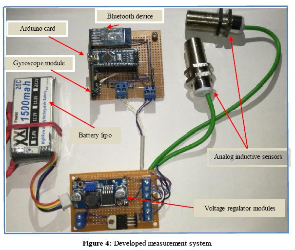
The full designed and developed measurement system for shaft alignment can be seen in Figure 2.
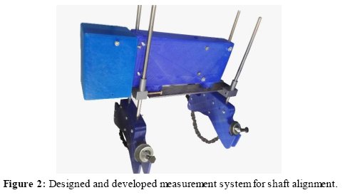
This measurement system is depicted by using inductive sensors, which without making contact on the couplings/axes of the rotating machines make the measurement of the distance of the sensors to a rigid reference bar, so that the difference between the readings of these sensors indicates the degree of misalignment. The measurement procedure has to be performed in three positions separated from each other (9, 12 and 3 clockwise) [17], the readers can be see details in Table 3. The Swedish company, SKF, [17], is on the front line with the developing of shaft alignment systems. Their work was an inspire source for our research project. . The developed system based on inductive sensors works with a data wireless shaft aligner, the readers can see details in the measurement set-up and procedure. The readers can see details in the measurement set-up and procedure part.
The alignment tolerances have been quantify and recommended for application by the Pruftechnik Company with more than 20 years in the field of industrial alignment equipment. It has a database of tolerances recommended for alignment [15], there can be found the recommended values for shaft alignment types and varying speed. It can be observed in Table 1, the reason to our selection method the Inductive sensors method, ultra-low cost, high accuracy, and easy to implement.
3. THE MEASUREMENT SYSTEM DESIGN: ELECTRONIC SYSTEM, MECHANICAL STRUCTURE, AND SOFTWARE
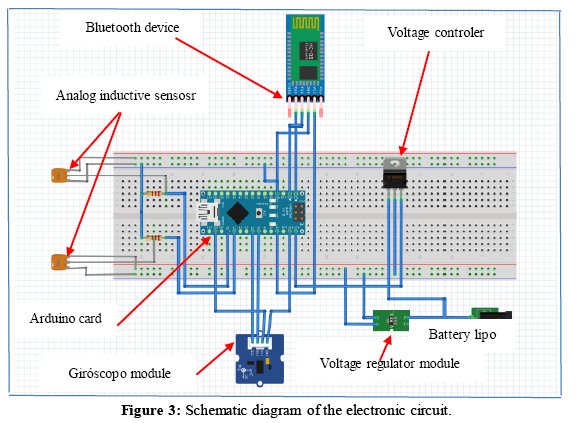
In this section, it will be performed an extensive study of the alignment measurement system design. The readers can also see the system components in details, in the measurement set up and procedure analysis. Figure 3 and 4 denote a schematic diagrams of the designed electronic circuit.
• Electronic Design: The data acquisition was performed with an Arduino UNO board, which is wide used microcontroller. It is equipped with sets of digital and analog pins, which can be applied as an interface to other expansion boards. According [17], the device has to measure in three different positions in direction of the clockwise, see details in Table 4. The MPU 6050 accelerometer module was implemented to allow software programming directly. The consumption of the electronic components in total is 112.8 mA, the Arduino Nano (19 mA), Module HC-05 (50 mA), MPU 6050 (3.8 mA), Inductive sensors (40 mA). Due to the autonomy of the developed system, requires a sufficient DC power supply in the devices to guarantee an appropriate operating time. The voltage levels of the components are variable (Sensors (15 - 30 Vdc), Arduino Nano (10 V), HC-05 (5 V) MPU-6050 (3.3 V) must be compensated by this power supply system. To achieve the voltage requirements, a LIPO battery, XL6009E1, and L7810 voltage regulator devices were installed. It can be concluded that the system operating autonomy is about 13 hours. The data wireless commutations between the measurement system and the computer were incorporate using a HC-05 Bluetooth communication device. The inductive sensors which measure distances have good precision, good repeatability be suitable for work in industrial environments and it has an affordable cost. The designed system were incorporate a pair of inductive distance sensors with Analog Output, SENSE PA4-18 GI50-AN. The sensors have a type of current output, and the data acquisition card receives signals at voltage levels, so Ohm's Law was used to find the value of a resistance and set a voltage level according to the entry of the DAQ. The calculated resistance value is 220 Ω to condition this signal.
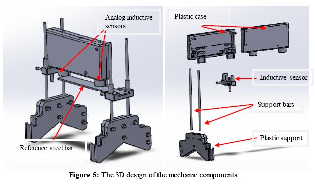
• Mechanical design: All the details of the 3D design can be seen in Figure 5. Solidworks was the software applied for designing of plastic structures, support bars, a metal chain and steel measurement reference.
• Software design: Figure 6 shows the framework of the software programming of the shaft alignment analysis procedure. The developed software for control Arduino Board , and the Matlab (GUI) collects the geometry information of the system to be measured, the input of distance variables the inboard feet of driver and outboard feet of driver. Thereafter, the data is calculated, according equations (6, 7, and 8), to give the values of the misalignment and their corrections values, respectively.
It was used throughout the analysis procedure, as reference the shaft alignment Handbook [2]. Figure 8 illustrates the nomenclature to be used in the mathematical modeling of the alignment analysis.
In Figure 8, A, B, C, D, and E are distances, N is the half of the difference of the near indicator (Near). F is the half the difference of the far indicator. Thereafter, the N and F readings should be compensated by the bending effect. Then, it can be determined the inboard feet and the outboard feet of driver by the following equations:

The inboard feet are the front support (leg), and the outboard feet is the back (leg) support the driver machine, respectively. Figure 9 shows points that are recorded by the inductive sensor P1 and P2, which can be observe in a coordinate plane. In principle the center point will be the coupling between the two machines. The correction values are related to the correction of the equations (1) and (2), to determine the correction values for the legs.
Therefore, using the point-point equation, the model for the coupling system and consecutively the values of the front and rear corrections can be found.
![]()
Then replacing the values obtained in the measurements could be the following:
![]()
where D is the distance from the first inductive sensor to the center of the coupling (Assuming that the coupling is located parallel to the center of the distance between dials D = C / 2). S12 is the reading of the dial located next to the stationary machine. M12 is the reading of the inductive sensor located next to the movable machine. Thereafter, the characteristic equation to find the alignment value is equation (4).
![]()
It should be noted that the location of the coupling with respect to the center of the sensor is variable, so the value that can take x, has to consider the distance to the coupling of the first sensor was placed. Then the value of x could be determined from the relation:
![]()
To calculate the correction values on the front and rear legs and the angular misalignment values, the following expressions are used:

4. MEASUREMENT SET-UP AND ANALYSIS PROCEDURE
The measurements were performed with the designed shaft alignment measurement system. The system was mounted on the driver and driving shafts connected by a flexible coupling system as it can be seen in Figure 10 (a,b,c).
It denotes the gearbox with the shaft and the respective supports. After the machine information typing the determine distances showed in Figure 10a). The software guides throughout the measurement analysis two inductive sensors measure the distance to the reference bar, Figure 10b). The recorded data from both inductive sensors can used as input data to the post processing in Matlab® and performing the alignment process. For case of completeness, this research work is to design and develop a shaft alignment system. Therefore all the details of the components and sensors are specified in table 2. The inductive sensors are considered to have good precision, good repeatability, be suitable for work in industrial environments and it is affordable cost.
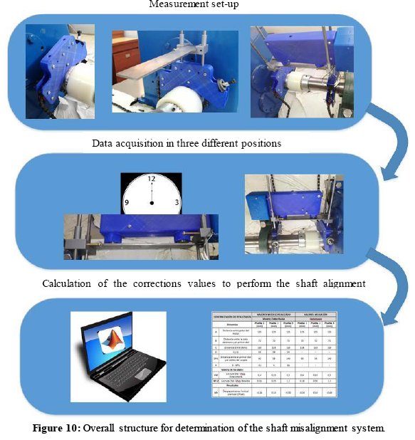
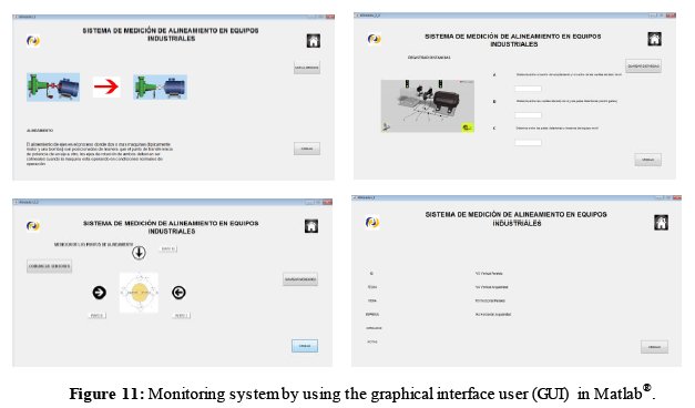
Figure 11 shows the monitoring system based on the developed the human interface machine, using Graphical Interface User (GUI) of Matlab. This is the software to be used for the alignment process. It starts with measurements of the machines geometrical values. Thereafter, the measurement procedure has to be performed in three positions separated from each other (9, 12 and 3 clockwise) [17]. Finally, the correction values are calculated in order to get an aligned rotating shaft.
For case of completeness, this research work is to design and develop a shaft alignment system. Therefore all the details of the components and sensors are specified in Table 2.
5. EXPERIMENTAL DATA ANALYSIS AND RESULTS
The designed system was mounted on the vibration analysis kit, with a gearbox, flexible coupling and shafts. To validate the designed measurement system the obtained measured data was introduced for comparison reasons to a standard software system named Fixturlaser. The obtained outcome has the same alignment accuracy for both methods. This means that the proposed method works at least between the standard and developed software. Table 3 illustrates the geometry distances of the measured system, the nomenclature can be seen in Figure 8.
It can be pointed out that in this research work the method applied is the Double Radial Method. It requires at least three measurements points on the rotating shaft. The designed software for the shaft alignment analysis procedure was carried out partly by the Arduino Board (data acquisition) , and Matlab® and (GUI) were used for the calculation of the alignment correction.
Experimental data with different configurations can be seen in Table 4. The experiments were performed in four groups, each group was measured in certain position rotating shaft degrees, specific at 9, 12, 3 and 9 clockwise, respectively. In order to find out the variability of the measurements, test group one and four, were carried out with the same misaligned measurements conditions.
The collected geometry information of the measured system was used as input data, distance variables, such as, the inboard feet of driver and outboard feet of driver. Thereafter, the data is calculated, according equations (6, 7, and 8), to give the misalignment corrections values. Finally, the overall average standard deviation of the experimental data set was about 0.02 mm, which is under the standard recommended values for alignment systems, see [15] for details.
6. CONCLUSIONS
Inadequate alignment of rotating shafts through couplings often leads to severe vibrations complications, with premature failure of couplings and bearings. An appropriate shaft alignment can reduce the existence of disproportionate radial and axial forces on the vulnerable parts of a machine system.
Based on the literature review, the method selected was the inductive sensor method for alignment of rotating machines. Therefore, the mentioned method was chosen to design and develop the whole measurement system in this research work. It was used an Arduino Uno for the data acquisition procedure and Matlab® and GUI for the data analysis. The performance and the effectiveness of the proposed measurement system was verified by an experimental procedure.
Finally, the shaft alignment system for industrial proposed in this research work was successfully developed and at low cost. The overall average standard deviation of the experimental data set was about 0.02 mm, which is under the standard recommended values for alignment systems.
8. ACKNOWLEDGEMENTS
The authors would like to express their gratitude to Universidad Privada Boliviana (UPB), for all the support to make possible this research project.
9. BIBLIOGRAFY
[1] A. Grall, C. Bérenguer, y L. Dieulle, «A condition-based maintenance policy for stochastically deteriorating systems», Reliability Engineering & System Safety, vol. 76, n.o 2, pp. 167–180, 2002.
[2] J. Piotrowski, Shaft alignment handbook, 3rd ed. Boca Raton: CRC Press, 2007.
[3] D. L. Dewell y L. D. Mitchell, «Detection of a misaligned disk coupling using spectrum analysis», Journal of vibration, acoustics, stress, and reliability in design, vol. 106, n.o 1, pp. 9–16, 1984.
[4] A. a Sekhar y B. S. Prabhu, «Effects of coupling misalignment on vibrations of rotating machinery», Journal of Sound and vibration, vol. 185, n.o 4, pp. 655–671, 1995.
[5] H. Cho y M. Jeong, «Enhanced prediction of misalignment conditions from spectral data using feature selection and filtering», Expert Systems with Applications, vol. 35, n.o 1-2, pp. 451-458, jul. 2008.
[6] I. Bravo-Imaz, H. Davari Ardakani, Z. Liu, A. García-Arribas, A. Arnaiz, y J. Lee, «Motor current signature analysis for gearbox condition monitoring under transient speeds using wavelet analysis and dual-level time synchronous averaging», Mechanical Systems and Signal Processing, vol. 94, pp. 73-84, sep. 2017.
[7] A.M. Knight y S.P. Bertani, «Mechanical fault detection in a medium-sized induction motor using stator current monitoring», IEEEE Transactions on energy convension, vol. 4, pp. 753-760, dic. 2005.
[8] M. Abd-el-Malek, A. K. Abdelsalam, y O. E. Hassan, «Induction motor broken rotor bar fault location detection through envelope analysis of start-up current using Hilbert transform», Mechanical Systems and Signal Processing, vol. 93, pp. 332-350, sep. 2017.
[9] B. Corne, C. Debruyne, P. De Baets, y J. Desmet, «Stator current measurements as a condition monitoring technologyThe-state-of-the-art», en Electrical Machines (ICEM), 2014 International Conference on, 2014, pp. 1659–1665.
[10] Nandi, S.; Toliya H.A, «Novel frequency domain based technique to detect incipient stator inter-turn faults in induction machines», vol. vol.1, no., pp.367-374 vol.1, n.o Industry Applications Conference, 2000, 2000.
[11] A. Simm, Q. Wang, S. Huang, y W. Zhao, «Laser based measurement for the monitoring of shaft misalignment», Measurement, vol. 87, pp. 104-116, jun. 2016.
[12] X. Zhang y H. Zhao, «A four-point quantitative detection method for shafts misalignment», en Ubiquitous Robots and Ambient Intelligence (URAI), 2016 13th International Conference on, 2016, pp. 921–925.
[13] W. Xinwei y M. Li, «The Design of a Simple Laser Shaft Alignment Instrument», 2010, pp. 653-655.
[14] A. G. Fulzele, V. G. Arajpure, P. P. Holay, y N. M. Patil, «Condition monitoring of shaft of single-phase induction motor using optical sensor», Mechanical Systems and Signal Processing, vol. 29, pp. 428-435, may 2012.
[15] Pruftechnik Company.«An engineers guide to shaft alignment, vibrationa anlysis , dynamic balancing & wear debris».2001 . [ Links ]
[16] Mobley Keith, Maintenance fundamentls. Butterworth-heinemann, 2004.
[17] Svenka Kullage Forening, «SKF TKSA 11 Manual de instrucciones alineador de ejes».2007 . [ Links ]
[18] H.E. Peña, Fallas en los motores eléctricos de induction, vol. III. 1994.
[19] Asea Brown Bovery, «Intruction manual for engineers ABB».www.new.abb.com/docs/librariesprovider53/about-downloads/ motors_ebooks.pdf?sfvrsn=4. 2015.

