


Servicios Personalizados
Revista

Articulo
 Inglés (pdf)
 Articulo en XML
 Referencias del artículo
 Enviar articulo por email
Indicadores
 Citado por SciELO
 Links relacionados
 Similares en
SciELO
Similares en
SciELO Compartir

 Permalink
Investigación & Desarrollo
versión impresa ISSN 1814-6333versión On-line ISSN 2518-4431
Inv. y Des. vol.2 no.14 Cochabamba 2014
ARTÍCULOS – INGENIERÍAS
VIRMS: A VEHICLE INFORMATION AND ROAD MONITORING SYSTEM
VIRMS: UN SISTEMA DE INFORMACIÓN VEHICULAR Y MONITOREO DE CARRETERAS
Fabio Arnéz and Alex Villazón
Centro de Investigaciones de Nuevas Tecnologías Informáticas – CINTI
Universidad Privada Boliviana
avillazon@upb.edu
(Recibido el 01 de noviembre 2014, aceptado para publicación el 17 de noviembre 2014)
ABSTRACT
Intelligent Transport Systems (ITS) are emerging technologies for building collaborative vehicular networks to increase road safety and to improve drivers experience. Unfortunately these technologies require heavy infrastructure to be deployed inside and outside the vehicle that is difficult to extend. In this article we present VIRMS (Vehicle Information and Road Monitoring System), an ITS that is based on low-cost and small footprint client and server infrastructure that was designed to increase vehicular security and reduce accident rates along highways. The VIRMS remote client device is an on board vehicle electronic device that gathers data from sensors and processes the collected data that is sent to the VIRMS server in order to keep drivers informed with precise context information through the detection and identification of events (accidents, traffic jams, bad weather conditions, etc.) along the roads. A prototype running tests on Bolivian highways show that VIRMS can give a technological answer to a real problem where road safety is one of the highest issues and cause of mortality.
Keywords: Intelligent Transportation System, Embedded System, Electronic Vehicle Device, Real-Time Operating System, Communication Protocol.
RESUMEN
Los Sistemas de Transporte Inteligentes (Intelligent Transport Systems - ITS) son tecnologías emergentes para el desarrollo de sistemas colaborativos vehiculares en red, que permiten mejorar la seguridad y la experiencia de usuario de los conductores. Sin embargo estas tecnologías requieren el despliegue de infraestructuras pesadas, costosas y poco adaptables dentro y fuera de los vehículos. En este artículo presentamos VIRMS (Vehicle Information and Road Monitoring System), un ITS basado en una infraestructura cliente-servidor de bajo costo y ligera que fue diseñada para mejorar la seguridad vehicular y reducir la tasa de accidentes en las carreteras. El cliente remoto VIRMS es un dispositivo vehicular embebido que recolecta, procesa y envía información de sensores hacia el servidor VIRMS para mantener informado al conductor con datos contextuales detectando e identificando eventos en las carreteras (e.g. accidentes, embotellamientos, bloqueos, etc.). El prototipo de VIRMS fue validado en carreteras bolivianas, mostrando que VIRMS puede ser una respuesta tecnológica al problema de seguridad vehicular, que es uno de los mayores problemas y causas de mortandad.
Palabras Clave: Sistemas de Transporte Inteligentes, Sistema Embebido, Dispositivos Electrónicos Vehicular, Sistema Operativo Tiempo-Real, Protocolo de Comunicación.
1. INTRODUCTION
Traffic accidents are a major cause of deaths and injuries worldwide and particularly in countries where there are deficiencies in the infrastructure, high-degree of misbehavior of drivers, and a poor o no technological support on the roads. In the case of Bolivia, in the past 10 years, the rate of accidents deaths has doubled, especially on the main roads of the country[1]. This increase is mainly due to the lack of a control system for penalizing perpetrated excesses and infringements and also the lack of efficient emergency attention services.
Intelligent Transportation Systems (ITS) are emerging technologies to build collaborative vehicular networks to increase road safety, where it is expected that applications of these systems allow communication of different electronic devices usually installed aboard of the vehicles to improve drivers experience[2]. According to their functionality, ITS applications have been classified into three main categories: safety, efficiency and comfort. Safety applications aim at reducing the severity and mortality risk of car accidents; efficiency applications intend to manage traffic flow, vehicle control and road monitoring; and comfort applications aim at providing entertainment and contextual information to passenger. Our research focuses on safety applications through the development ofcustom hardware and software.
Regarding vehicles communication to the outside world, the communication mode is divided into two types: Vehicle-to-Vehicle (V2V) and Vehicle-to-Infrastructure (V2I) communications. The de-facto standard for V2V communication, the IEEE 802.11p[1], adds wireless access in vehicular environments following the vehicular ad-hoc network (VANET) approach. However, IEEE 802.11p suffers from scalability issues, unbounded delays and short radio range that unleashes in the lack of Quality of Service (QoS) guarantees[3], which limits its applicability for V2I communications. These limitations have motivated the recent increasing interest in cellular network infrastructure communication technologies like Universal Mobile Telecommunications System (UMTS) and Long Term Evolution (LTE) as a promising approach for V2I communication.
In this article we describe VIRMS (Vehicle Information and Road Monitoring System) a safety-oriented ITS. VIRMS wraps inside advanced electronics technology and uses existing telephony network to achieve V2I communication. It contains components of software and hardware that allows collecting, process, store and retrieve accurate and relevant information to meet the safety needs of drivers along the roads. In addition, it can assist emergency services with rescue institutions or the highway patrol to control possible excesses and infringements from drivers. In this article, we focus on describing the VIRMS Remote Clients hardware and software components. The VIRMS Remote Client implementation is compact and inexpensive because it uses conventional mobile networks for information exchange and is based on Embedded Electronic Systems for data processing aboard the vehicle. The contribution of this article is threefold:
● We present an ITS based on hardware and software components with a small footprint and low-cost.
● The ITS uses existing mobile phone network with low bandwidth requirements.
● A working prototype showing the feasibility of the approach that was tested in Bolivian roads.
The rest of this article is structured as follows: Section 2 depicts the overall VIRMS architecture. The description of both hardware and software components of VIRMS Remote Client are presented Section 3. Section4 presents the implementation details and experimental results of the VIRMS prototype, whereas Section 5 discusses advantages and disadvantages of VIRMS. Related work is presented in Section 6. Section 7 concludes the article.
VIRMS follows a client-server architecture, where the clients are embedded systems deployed in vehicles and connected to the server through a cellular network over the Internet. The onboard VIRMS Remote Client comprises hardware and software to collect information through different sensors and geo-location data through a GPS antenna, and delivers context information to the VIRMS Central server. The server exchanges information with all deployed VIRMS Remote clients, to keep users (i.e. drivers) informed with relevant context information. Figure 1 depicts the VIRMS ITS architecture showing the two subsystems.
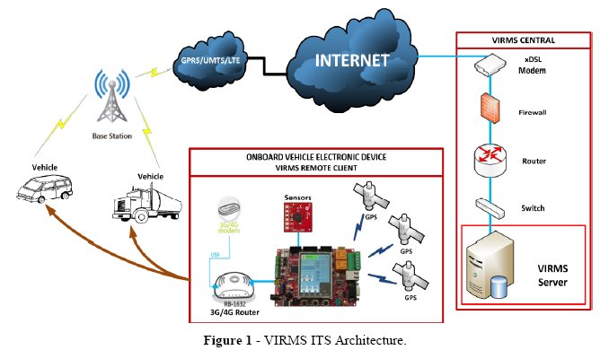
The VIRMS Remote Client consists of an advanced embedded electronic system whose functions are to collect, process, store and retrieve accurate and relevant information to satisfy the drivers needs throughout the country roads. It communicates with the VIRMS Central to exchange selected context information, including state of roads, weather conditions, traffic, blocking roads points, existence of accidents, requirement of technical assistance and state of danger or panic of drivers along roads. To fulfill these requirements, the architecture of the VIRMS Remote Client follows the recommendations presented in[4]which intends to help future emergency and rescue services.
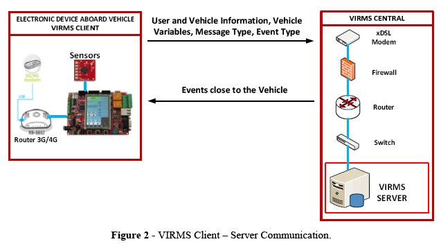
The VIRMS Central hosts the VIRMS server and provides Internet connectivity (e.g. through axDSL modem). The VIRMS server receives requests, processes and sends back a response to the clients. Due to the limited computational resources on the embedded clients (processing capabilities and memory), the designed communication protocol was strongly simplified, so as to avoid complex data parsing and interpretation. On the server side however, no such restriction is present, so that more advanced processing is performed on data such as database handling to store the received information, filtering and query back of information required by the clients. Figure 2 shows the communication scheme between the VIRMS client and server. The client sends information (to the server) about the user/driver, vehicle variables, a message type and event types. The server sends back to the client the events near to the vehicle. The message type field tells the server if the client is reporting events or not. Possible event types that the user can report include poor state of the road, bad weather, heavy traffic, road accident and blocked roads.
The following section explains in detail the client side, since it has hardware and software components that enable main features of the whole VIRMS Intelligent Transportation System.
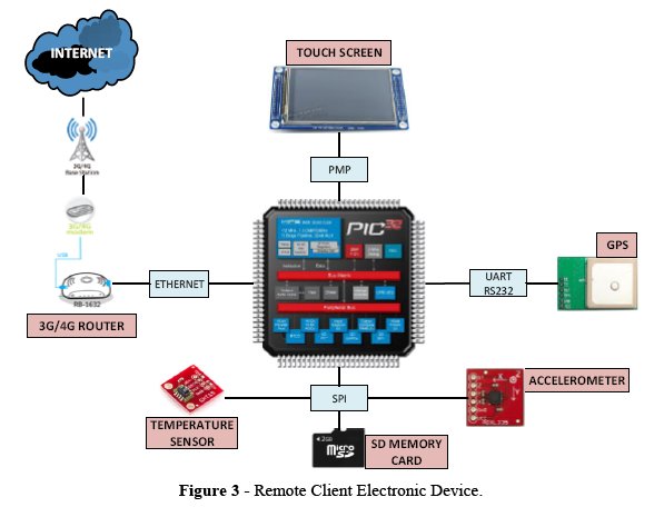
The VIRMS Remote Client is an embedded system composed of hardware and software components that were developed to meet the requirements of our ITS. The architecture of the VIRMS Remote Client is depicted in Figure 3. The electronic system incorporates a 32-bit PIC32 microcontroller unit (MCU) from Microchip[2], which communicates and interacts with various peripherals as follows:
● GPS Module: to obtain the vehicle speed and geo-location data. It uses the Universal Asynchronous Receiver and Transmitter (UART) communication interface.
● Accelerometer: to estimate vehicles spatial orientation. It uses a Serial Peripheral Interface (SPI).
● Temperature Sensor: to identify possible onboard firesafter a crash. It uses a SPI interface.
● Color Touchscreen: To Interact with the vehicles driver through a Graphical User Interface (GUI). It uses a Parallel Master Port (PMP) interface.
● SD Memory Card: to store road maps to be displayed in the GUI, and activity log information.
● Ethernet Communication Module: to allow the device Internet connection and communication to the VIRMS Central through a 3G modem and Router.
Due to the large amount of tasks that the MCU must handle, the different priorities needed for the embedded system to function properly and time constraints that must be satisfied, we decided to deploy the VIRMS Remote Client using a Real-Time Operating System (RTOS). The RTOS is in charge of the task order execution given their priorities and the time assigned to each one. It also provides some guaranties in the execution of the operations that are handled differently from a conventional operating system, notably the processing of data in real-time, i.e. without buffering as it is produced. The RTOS also handles the mechanisms to communicate and pass information between tasks[5]. There is a large set of commercial and non-commercial RTOS for the Microchip PIC32[3]. We chose FreeRTOS[6] for the development of the VIRMS Remote Client due to its open source nature, small footprint, community support and fulltask handling support. The programming interface for the development of the Remote Client embedded device is standard C programming language, which allows implementing fast applications with small footprint.
When using an RTOS, we should create and manage tasks instead of following a purely sequential programming. The task abstraction allows designing independent execution flows associated with priorities. Tasks communicate between each other using queues and they can share common resources (memory sections or peripherals). For this reason, they must be synchronized through the use of mutual exclusion mechanisms, namely mutexes.
For the VIRMS Remote Client embedded system device six fundamental tasks have been identified:
● TaskIO: Task for the MCUs Inputs and Outputs management
● TaskGPS: Task for GPS frame parsing
● TaskGUI: Task for Graphical User Interface (GUI) interactions
● TaskTCPIP: Task for networkcommunication
● TaskSENSE: Task for sensor data reading(from accelerometer and temperature sensors).
● TaskSD: Task for the memory card interaction
Figure 4 shows the tasks ordered according to their priority. The task priority was assigned according to the importance and the need of processor time. The first three tasks (TaskIO, TaskGPS and TaskGUI) are intended to run immediately and the last three tasks (TaskTCPIP, TaskSD and TaskSENSE) are executed with a certain frequency (periodic tasks). In FreeRTOS the highest priority is assigned with the highest value from a used range of values. The systems highest priority is 4 and the value is assigned to the tasks that require constant and immediate attention and must handle and process the most important information. In our case, I/O operations and accessing data from the GPS are handled with the highest priority. When tasks share the same priority value, the scheduler assigns the same processor time slice to each one.
The VIRMS_DATA data structure (see Figure 5) is used for data exchange of the generated user information between tasks.
The data structure is used for inter-task communication holds the following information: user and vehicle information introduced by driver (lines 3-5); the GPS received information (lines 7-2); the accelerometer and temperature sensor data (lines 24-27); data type conversions of the received GPS latitude and longitude for navigation purposes that require floating point calculations[4] (lines 29-38); and the message type and the events to be sent to the VIRMS server (lines 40-41).
The VIRMS_DATA structure is accessed through data queues in a shared memory segment. The interacting tasks use mutexesto guarantee synchronized access to the data structure during runtime. Figure 6 depicts the inter-task data flow and task-memory interactions. TaskIO interacts with the MCU inputs and outputs and sends the received data from the GPS module and the touch commands (from the touchscreen) to TaskGPS and TaskGUI respectively; TaskGPS extracts the relevant and required information received from the GPS module and writes into the data structure; TaskSENSE reads data from the accelerometer and temperature sensors and then writes into the data structure; TaskGUI receives the touch commands from the TaskIO and translates them for the user interaction with the graphical interface, this task also reads information from the data structure to show it into the graphical user interface; TaskSD reads the data structure to write the system logs into the external memory card; Finally TaskTCPIP reads and writes the data structure to send the remote client device information to the server and to store the context information received information from the server respectively.
Figure 7 shows the flowchart of the main function of the program developed for the VIRMS Remote Client. The first stepis the initialization of the microcontroller hardware (System Initialization), followed by the initialization of all tasks with the associated priorities(Task Initialization) and finally the initialization of the RTOS Scheduler (Scheduler Initialization).Once all tasks are ready for execution the kernel determines which tasks are executed and when according to their priorities. The main function will terminate (i.e. reach the END state) only if there is insufficient heap memory, the user interrupts scheduler action, or un-handled critical errors are presented along the general runtime execution. During execution, every task performs a set of instructions to read, write or transfer data.
3.1. TaskIO
This task allows receiving the information from the touchscreen when it is pressed by the user and also analyzes the UART port interface. If there is data available in the UART receptor (GPS module communicates with the MCU trough UART interface), the task stores the received data in a 10 bytes memory buffer. Once the memory buffer is full, the task sends the data through a queue to the TaskGPS task for further processing.
3.2. TaskGPS
This task allows saving the received NMEA[5] frame characters from the GPS module. Among other information, the collected data contains the GPGGA (Global Positioning System Fix Data) and the GPRMC (Recommended minimum specific GPS/Transit data). The first one contains for example, information about time, latitude, longitude, number of satellites, altitude and checksum. The second one contains additional information about date and speed. The data frames are stored in the 500 bytes memory buffer that intends to store all the GPS NMEA frames in a burst (every GPS burst occurs once per second). When the desire frames are found, each one is copied to an independent memory buffer for specific parsing to obtain the desired data. Figure 8 shows an example of the GPS buffer and the frames stored in independent buffers.
3.3. TaskGUI
This task is responsible for displaying all the graphical elements in a color display (16 bits) for user interaction with the electronic device. The main elements to be displayed can have buttons, windows, check boxes, text boxes and images (which are read from an external memory card). This task will also receive and interpret the messages sent by the touch screen(function running in TaskIO) to indicate the elements with which the user interacts.
Figure 9 depicts the screen states for the Graphic User Interface (GUI). The initial state is represented by the Splash Screen state. The subsequent states are of two types: Create and Show. The Create-type states are those responsible for instantiating all graphics objects needed to allow user interaction whereas the Show-type states display those objects. The transition between Create and Show states is implicit (i.e. no explicit event triggering a state change state). State transition is performed automatically when all objects are ready to be displayed. Once the screen changes, the MCUmust delete all graphics objects from memory and then create new graphical objects for the next screen. This is due to the limited amount of memory, which usage needs to be optimized by the MCU. Finally the Show-typestates remain showing their graphical objects until the user performs an action to change the screen. Similar implicit cleanup is performed on the memory frames as well.
TaskGUI handles several screens to interact with the user to gather input data or to display information received from the VIRMS Central server. The interactions triggering the creation or display of the other screens (after the very first Splash Screen)are shown in Figure 9.
The following screens are handled by the GUI:
● User Login Screen: Allows the user to enter a personal code, the current vehicle plate and route. After filling the required information the user must press the Accept button to continue to the User Menu screen.
● User Menu Screen: Allows the user to choose among the VIRMS ITS features. Here the user can access to a context Information screen, a screen for Event Report, and screen for localization and navigation that shows a static map.
● Information Screen: The main purpose of this screen is to inform the vehicle driver about what is going on around, this means that the VIRMS Remote Client devices provides useful context information for the driver. This screen shows the data entered data by the user in the User Login Screen, the current time and date and the events around the vehicles. The events are: poor state of the road, bad weather, heavy traffic, road accident and blocked roads.
● Event Report Screen: Allows the driver to report events that occur near the vehicle. The events that can be reported are the same as the previous screen (information screen): poor state of road, bad weather, heavy traffic, road accident and blocked roads. In addition the user may report that requires technical assistance and also if it senses danger or feels threatened.
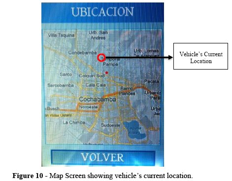
● Navigation Screen: The main function of this screen is to provide the driver a basic navigation and localization service. The screen shows a static map of 220x220 pixels that represents a geographically square type map segment with 10 Km side, which shows the vehicles current location.
The maps (in JPEG[6]format) are pre-stored in a Secure Digital memory card(SD card) and are loaded into memory on an on-need basis. This is because the MCU memory capacity is very limited and cannot store large amounts of data such as several images at the same time. Additionally, the high communication latency due to the type of Internet access (mobile network) does not offer an optimal solution to load maps directly from an online service such as Google Maps[7], together with the lack of appropriated API (Application Programming Interface) to access maps from a C programming interface of the MCU. Such an interface is limited to static access to map images, which is therefore equivalent to our solution based on pre-stored map images on the SD card.
In order to display the image on the screen it is necessary to read the image from the SD cardand then decode the JPEG image format, so as to correctly display the image buffer on screen. The current coordinates read from the GPS are used to load the correct image of the map, which is at a fixed scale. The bottom left (x1, y1) and top right coordinates (x2, y2) are known for each image (to simplify, we use those coordinates to search the name of the map files stored on the SD card). When the received GPS coordinates are read (xcurrent, ycurrent), we are able to identify which map to be loaded, based on the current location. Whenever the current coordinates are out of bound, we load the corresponding map accordingly.
To indicate the current location in the map, we overlay a red spot indicator by modifying the image buffer to be displayed. Figure 10 depicts the vehicles current location represented by point as a spot in the map. While (xcurrent, ycurrent) is within the map delimited by (x1, y1) and (x2, y2) we need to calculate the relative position where to display the red spot at P(x,y). The translation calculation is given by equations (1) and (2). The first equation calculates the translation of the received GPS latitude and the second equation calculates the translation of the received GPS longitude. On both equations the MAP_WIDTH and MAP_HEIGHT are equal to 220 in our case (i.e. the size of the image). Finally,the MAP_X_OFFSET is equal to 10 for the first equation and the MAP_Y_OFFSET is equal to 270 for the second equation. The offset values are obtained from the margin pixels around the map image so as to make it centered into the window container.

3.4. TaskTCPIP
This task is responsible for initializing and managing the TCP/IP protocol stack to provide Internet connectivity to communicate with the VIRMS server. The network configuration relies on a DHCP[8] server (for automatic settings), a service that is provided by the 3Grouter connected to the MCU. The TaskTCPIP also handles the link layer MAC address configuration and provides the interface to create network sockets to interact with the VIRMS server. The VIRMS protocol is based on TCP for reliable communication. Once the connection is established and the data is sent and received, the information is stored in the allocated VIRMS_DATAstructure. Note that the architecture of RTOS forces any other task requiring network connectivity to explicitly delegate all communication to this task, which implies additional programming effort to correctly handle communication between tasks and through the network. Finally, this task is scheduled to be executed every 4 seconds to avoid high volume information upload to the server.
3.5. TaskSENSE
This task allows the communication between the MCU and the Bosch SMB380 module[9]that encapsulates a tri-axial accelerometer and a temperature sensor. The communication uses a SPI interface where the MCU is the master and the SMB380 is the slave. This task is executed every 200 milliseconds by adding a special RTOS timing function that prevents inefficient processor waiting while the desire time ends. The sampling period was defined from the sensors specification datasheet, which additionally prevents processor overloads that may result in a task starvation situations or priority inversions.
3.6. TaskSD
This task allows the MCU to store all the collected and generated information into an external SD memory card. For this purpose the task creates a text file in the SD memory card. The task access to the user data structure and retrieves the most important data fields to write them into the created text file. The purpose of the stores text file is twofold: It serves as a data logger to post-mortem analysis of events happening in the VIRMS Remote Client and it also serves as a mechanism for non-volatile storage for data recovery in case of a crash. It is important to note that TaskSD and TaskGUI share the same interface and hence the same resource (i.e. the SD memory card).
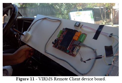
We developed a board containing the embedded electronics of the VIRMS Remote Client(see Figure 11) and measure the system in real world conditions. The embedded electronic device was connected the cell phone network through a 3G router and modem. The VIRMS Central was developed using Java Servlets technology[7]and was deployed in an Intel i7 computer with 4GB of RAM and running Ubuntu Linux 14.4.0. The Server was connected to the Internet through a local ISP (Internet Service Provider), which provided a fixed IP address. For the electronic device setup, the server IP address and the port were set into the electronic device microcontroller program. When the electronic device is turned on the driver must fill the requested information. The user request information fields are: user code, vehicles plate, vehicles route (destination). This information is stored in the VIRMS server and is used to send context information back.
4.1. Test Scenario
The VIRMS tests took place in the National Highway number 4, in a road segment within the metropolitan area of 16 Km long between the cities of Cochabamba, Colcapirhua, Quillacollo and Vinto. Figure 12 depicts the vehicle position (latitude and longitude) during the tests. The map was generated together with the path using the vehicles information stored in the VIRMS server database. One can observe a given number of the interruption in the plotted paths that are due to mobile internet connection loss, which mainly happened while changing or switching between mobile base stations or where there was weak service coverage.
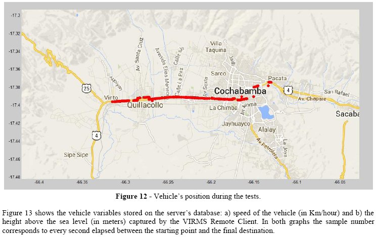
Figure 13 shows the vehicle variables stored on the servers database: a) speed of the vehicle (in Km/hour) and b) the height above the sea level (in meters) captured by the VIRMS Remote Client. In both graphs the sample number corresponds to every second elapsed between the starting point and the final destination.

VIRMS information can be used to identify possible drivers excesses and infringements of speed limits. Also abrupt changes in speed could warn about events like collisions or car falls to rescue institutions for fast and efficient emergency attendance along the roads. To distinguish between those events and normal behavior, e.g. related to speed reduction due to traffic lights, the VIRMS server checks the received data from the accelerometer (X, Y and Z axis values) to discard false positives. Such type of the speed decreases can be observed in Figure 13a) which corresponds to stops due to red traffic lights along the road. Figure 13b) showing the vehicles height is consistent since the cities in the test scenario round the 2600 meters above sea level. Concerning the speed and height drops around sample numbers 70 and 420; those are due to connection losses while switching between mobile stations. To discard misinterpretation of a sudden height difference (around 50 and 40 meters respectively) as an accident, VIRMS uses additional available data such as timestamps and accelerometer information to discard false positives.
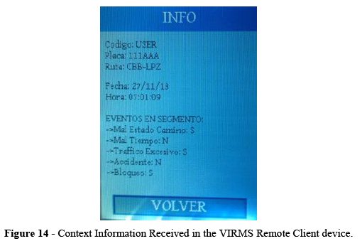
Figure 14 shows a screenshot of context information received from the Server into the VIRMS Remote Client during the tests. The first text group of shows user and vehicle information; the second group of text fields shows the current time and date; and the last group of text fields, shows information received from the VIRMS server that contains the events near the vehicle (poor state of the road, heavy traffic or blocked road).
4.2. Prototype cost
One of the main concerns of ITS development is the cost of the embedded devices on board of the vehicles. During the development of VIRMS, cost efficiency was an important goal to reach, because VIRMS targets mainly the Bolivian marketplace where cost is a real issue. TABLE 1 shows that we have reached our goal with a prototype cost of less than 200 USD. The higher cost corresponds to the electronic development (more than half of the price), followed by the Communications components (Mobile modem and Router), and finally by the GPS module. It is important to note that a mass production can significantly reduce the costs of VIRMSs Remote Client devices, making it more accessible and widely available.

5. DISCUSSION AND FUTURE WORK
VIRMS not only supports traditional GPS tracking system features (generally applied for post-crash attendance), it also allows the driver to be well informed due to the ability to exchange information between the VIRMS client and server for a certain location. The exchanged information represents relevant context information that could prevent accidents by warning drivers of what is happing around them. The systems also allows to attend accidents efficiently by identifying them faster and also institutions like Police can identify drivers excesses and infringements due to the generated logs for each car with the VIRMS Remote Client onboard device.
One of the current problems of VIRMS is the high volume of information generated within each client, resulting in ahigh amount of data in the servers database. To mitigate this situation, further development will focus on efficient storage and communication of information. Also, context information currently sent to the VIRMS Remote Client only refers to the segment where the car is located. An extension on the communication protocol can enable to enhance this information, e.g. by sending context information of neighbor segments and including more metadata to inform the driver. We will explore such enhancements that are complementary to the existing VIRMS prototype.
To summarize, VIRMSs current and future development focuses on four areas: The remote client hardware, ITS software applications, communication security and the server side software enhancements. For remote client hardware we are exploring additional forms of client technology, e.g. other types of embedded systems and the development of a smartphone application remote client. The later seems a promising approach because smartphones hardware has most of the required components (GPS, sensors, screen, network connectivity) and eases the map and navigation integration and handling. For ITS software application we aim at developing a notification service to enhance user experience, because currently the context information is displayed on user request only. For communication security, VIRMS will be enhanced with Secure Socket Layer (SSL) for client – server communication. Finally, server side software enhancements include a web service based API (Application Programming Interface) to simplify the interactions between clients and server and the ability to show multiple remote clients and also to identify events automatically along the roads.
OnStar[6]is an example of post-crash ITS. OnStar is a subsidiary of General Motors that provides subscription-based communications, in-vehicle security and navigation. OnStar relies in CDMA mobile technology for data and voice communications and this service mainly allows automatically detecting events like collisions and notifying OnStar call centers for faster emergency attention.
The European Union has launched the eCall[8] intiative to build systems to bring fast assistance to drivers involved in collisions anywhere in the European Union roads. In case of a crash, an e-Call electronic device installed in a car, should automatically call the nearest emergency center. If no passenger is able to speak, a minimum set of data is sent, which includes the exact location of the collision event.
Both eCall and OnStar are very similar. A vehicle collision activates the on-vehicle sensors, causing an emergency call to be initiated, if there is not a passenger able to speak additional relevant information is sent to call centers. Unlike eCall, OnStar also provides an on-road navigation system. However eCallis more ambitious since it is expected to support all brands and types of vehicles in the European Union region, while OnStar is only supported by General Motors vehicles in only a few countries[4].
OnStar and eCall initiatives require expensive infrastructure and both use closed communications protocols and hardware technology. VIRMS, on the other hand is easier, but more suited to be deployed in countries like Bolivia. In fact, the Bolivian government launched a initiative for inter-departmental buses for road safety increase, which uses a GPS based tracking system, but this initiative has not achieved the intended deployment and hence the expected safety increase due the high cost of the client electronic devices and their limitations in hardware and software since this devices mainly send GPS data to a server for car tracking (one way communication) and do not incorporate a GUI.
In this article we presented VIRMS, an ITS based on low-cost and small footprint client and server. VIRMS does not require special networking infrastructure, as it uses existing mobile phone network for internet access for client-server communication. The VIRMS remote clientuses bi-directional communication and information to send and receive information about traffic events. Our prototype implementation shows that VIRMS provides the basic functionalities to build road safety services.The working prototype was deployed and tested in Bolivian roads showing the feasibility of the approach.
8. REFERENCES
[1] Instituto Nacional de Estadisticas. Instituto Nacional de Estadisticas. [Online]. Avaible: http://www.ine.gob.bo/indice/EstadisticaSocial.aspx?codigo=30903 [ Links ]
[2] K. Dar et al. "Wireless communication technologies for ITS applications [Topics in Automotive Networking]," Communications Magazine, IEEE, vol. 48, no. 5, pp. 156-162, may 2010.
[3] G. Araniti et al. "LTE for Vehicular Networking: a Survey," Communications Magazine, IEEE, vol. 51, no. 5, pp. 148-157, may 2013.
[4] F.J. Martinez et al. "Emergency Services in Future Intelligent Transportation Systems Based on Vehicular Communication Networks," Intelligent Transportation Systems Magazine, vol. 2, no. 2, pp. 6-20, 2010.
[5] D. Ibrahim. Advanced PIC Microcontroller Projects in C: From USB to RTOS with the PIC18F Series. Oxford, Oxford: Newnes, 2008.
[6] Real Time Engineers Ltd. (2013) FreeRTOS Quality RTOS & Embedded Software. [Online]. Avaible: http://www.freertos.org [ Links ]
[7] Java Community Process (JPC). (2009, Dec.) JSR 315: JavaTM Servlet 3.0 Specification. [Online]. Avaible: https://jcp.org/en/jsr/detail?id=315 [ Links ]
[8] European Comission. Digital Agenda for Europe - ECall. [Online]. Avaible: http://ec.europa.eu/digital-agenda/en/ecall-time-saved-lives-saved [ Links ]
[9] General Motors. OnStar. [Online]. Avaible: http://www.onstar.com [ Links ]
NOTAS
[1] An approved amendment to the IEEE 802.11 standard to add wireless access in vehicular environment [http://standards.ieee.org/findstds/standard/802.11p-2010.html]
[2]http://www.microchip.com/pagehandler/en-us/family/32bit/
[3]http://www.microchip.com/devtoolthirdparty/ThirdpartyListing.aspx?catId=809fe361-a1b9-41ce-bde7-821ba59ffdb4
[4] The information to compute the floating-point operations is directly in-lined in the VIRMS_DATA structure, so as to avoid creating other structure for inter-task communication. This also prevents repeated computations.
[5] NMEA stands for National Marine Electronics Association. This association developed a specification that defines the interface between marine electronic equipment. GPS receiver communication is defined with this specification. More information at: http://www.gpsinformation.org/dale/nmea.htm
[6] JPEG stands for Joint Photographic Experts Group (http://jpeg.org/jpeg/)
[7] http://developers.google.com/maps
[8] DHCP stands for Dynamic Host Configuration Protocol allowing automatic configuration over the network, and is defined as an Internet standard in RFC 2131 (http://tools.ietf.org/html/rfc2131)
[9] http://header.bosch.com/claim/ifl/framework/fallback.asp?component=productspecial&id=smb

