


Servicios Personalizados
Revista
Articulo
 Inglés (pdf)
 Articulo en XML
 Referencias del artículo
 Enviar articulo por email
Indicadores
-
 Citado por SciELO
 -
 Accesos
Links relacionados
-
 Similares en
SciELO
Similares en
SciELO
Compartir

 Permalink
Investigación & Desarrollo
versión impresa ISSN 1814-6333versión On-line ISSN 2518-4431
Inv. y Des. vol.1 no.14 Cochabamba 2014
ARTÍCULOS –INGENIERÍAS
HEAT RECOVERY SYSTEM IN AN INDUSTRIAL FURNACE TO GENERATE AIR CONDITIONING THROUGH AN ABSORPTION CHILLER
SISTEMA DE RECUPERACIÓN DE CALOR EN UN HORNO INDUSTRIAL PARA GENERAR AIRE ACONDICIONADO A TRAVÉS DE UN CHILLER DE ABSORCIÓN
Juan Pablo Vargas Bautista[1]
Tecnológico de Monterrey, ITESM, Campus Monterrey, México
jpvargas@upb.edu
(Recibido el 19 de febrero 2014, aceptado para publicación el 19 de marzo 2014)
A case study of a Heat Recovery System is performed in an industrial furnace that uses natural gas to determine the absorption cooling capacity (LiBr – Water) that can be generated for air conditioning. The energy source will be the heat of the flue gas that is eliminated by the furnace stack. Thermodynamic and economic analysis of the entire system (heat recovery exchanger, absorption chiller, cooling tower, etc.) is performed. A methodology to evaluate the Heat Recovery potential of the industrial furnace will be shown, as well as the limitations that must be considered. This methodology also considers the favorable environmental impact that is available to perform a heat recovery project. The results show that under certain operational characteristics and conditions, the heat recovery system is technically and economically feasible (profitable).
Keywords: Heat Recovery, Absorption Chiller, Air Conditioning, Energy Savings.
RESUMEN
Un caso de estudio de un sistema de recuperación de calor es realizado en un horno industrial que consume gas natural, para determinar la capacidad de refrigeración que puede ser generado para aire acondicionado utilizando un equipo de refrigeración por absorción (LiBr-Agua). Se utiliza los gases de combustión que salen de la chimenea como fuente primaria de energía. Un análisis termodinámico y económico de todos los equipos del sistema (recuperador de calor, chiller de absorción, torre de enfriamiento, etc.) es realizado. Se presenta una metodología para evaluar el potencial de recuperación de calor del horno industrial, así como también las limitaciones que deben ser consideradas. La metodología también considera el impacto ambiental favorable que se tiene del proyecto de recuperación de calor. Los resultados demuestran que bajo ciertas características de operación, el sistema de recuperación de calor es técnica y económicamente factible de realizar.
Palabras Clave: Recuperación de Calor, Chiller de Absorción, Aire Acondicionado, Ahorro de Energía.
1. INTRODUCTION
Energy plays an important role in supporting our daily life, economic development and every human activity. Energy systems are complex as they involve various technical, economic, environmental, legal and political factors. Due to the limitation of fossil energy resources, the impact on the environment and the human health problems during the last decades, therehas been a growing interest on developing, modeling and optimization strategies for energy systems. In this challenging scenario, old technologies like absorption cycles have emerged as a promising alternative in cooling and refrigeration applications, as they use refrigerant with zero global warming potential that do not contribute to the ozone layer depletion. Moreover, another advantage of these systems is that they can use different forms of primary energy source such as fossil fuels, renewable energy sources, and also waste heat recovered from other thermal systems.
Siderurgic industry has industrial furnaces that consume considerable amounts of natural gas to heat the iron slabs that enters to the furnace at atmospheric temperature to be heated at 1,250 °C and then they are sentto other process to be laminated; this kind of equipment has its own heat recovery that preheat the air before to enter to the combustion chamber, this heat recovery improves the efficiency of the equipment, but still the flue gases eliminated by the stack to the atmosphere have temperatures in the range of 250 to 400 °C that can be recoveredto generate a useful energy, not only for the process but also for other energy requirements in the plant, in this case to heat water in a heat exchanger and generate chilled water using an absorption chiller to supply air conditioning to the offices that are near the equipment.
The objective of this project is to demonstrate that it is technically and economically feasible to build a heat recovery system to generate air conditioning through a Lithium Bromide – Water absorption chiller of single effect driven by hot water. The flue gases of the industrial furnace will be used as a primary energy source.
Gebrelassie et al.[1] mention that absorption chillers have smaller COP (coefficient of performance) than conventional vapor compression cycles (5:1) for that reason absorption chillers require a higher number of units, which leads to higher investment costs. Hence, there is a clear need to develop strategies capable to optimize their design and operation from thermodynamic and economic points of view so they can become a real alternative to the standard compression system
Figure 1 shows different equipment that can be used to recover the flue gases and generate hot and cold water for air conditioning.
When heat is recovered from a process, e.g. an industrial process or a power production process, it is generally obtained at temperature which is too low for immediate application in the same process. This heat may instead be cascaded to a second process with lower requirements or heat quality i.e. temperature, or upgraded by transformation e.g. using a heat pump.
Important considerations used in this studyto evaluate a heat recovery project are:
→ Which are the waste heat sources available?
→ What amount of heat is available?
→ What is the temperature of the available heat?
→ What is it (substance)?
→ Can it be recovered?
→ Where it can be used this heat?
→ What amount of heat is required and at what temperature?
→ What portion of the available heat can be used?
→ When is it available? (Continuous, batch mode)
→ Is technical and economical feasible recover the waste heat?
→ What extra benefits can be obtained? (energy savings, environment issue, efficiency improvement, etc)
• State of the Art
Exhaustive searches of heat recovery systems and absorption chillers application driven by waste flue gases have been made in order to find similar projects. There is work done in absorption chillers [2], [3], [4], in cogeneration [5], [9], [10], and trigeneration recovery systems [6], [7], [8], [11] that use absorption chillers bases on thermal analysis, economic analysis and exergy analysis. There are studies about absorption chillers technology [12], [13], [14].
A literature survey shows that heat recovery systems have been analyzed as cogeneration and trigeneration systems based on gas turbines and/or combustion engine equipment. This article will focus on analyzing from a thermodynamic and economical point of view the combined production of heat water for air conditioning using the flue gas of an industrial furnace as a primary energy.
2. PROBLEM STATEMENT
The problem is the waste of heat through the flue gases of an industrial furnace and the principal objective is recovering the heat and produces a useful energy. There are a lot of companies and industries of warm and tropical regions that experiment an increase in the electricity demand during the summer period and sometimes they exceed the limit of the supply capacity.
The case of study was performed in Monterrey, Mexico in a well-known siderurgic industry company Ternium. The company needs 1,000 TR of refrigeration to cover the requirements of air conditioning for its offices; they use conventional vapor compressor and centrifugal chillers. The monthly cost for the electric energy is approximately 14,429 U$D considering an average COP = 3; 200 hr/month; 0.06 U$D/kWh. For calefaction the company uses boilers to heat the water and send it to the offices, the monthly cost for the fuel (natural gas) is approximately 21,600 U$D considering 12 U$D/MMBtu(11.37 U$D/GJ), 150 hr/month. The city of Monterrey has in average 9 months of warmth weather and 3 months of coolweather, which means a total energy cost of 194,661 U$D/year to cover the heating and cooling demand. This study will show under what conditions the project is thermodynamically and economically feasible. The study can be easily extrapolated to other geographical regions.
• Description of the Industrial Furnace
Figure 2 shows the industrial furnace that heats the iron slabs (6x1x0.25 meters). Iron slabs enter the furnace at atmospheric temperature (25 °C) and leave it at 1,250°C which is the ideal temperature to laminate the iron slabs. To reach that temperature the equipment consumes natural gas that is burned with preheated air and burn up in different points through the large of the furnace. The industrial furnace is programmed to work all year long with periodical maintenance without turning off the equipment. The major maintenance is done once a year and can take two weeks with the equipment switched off. The furnace has a SCADA monitoring system that allows obtaining the necessary data for the evaluation of the heat recovery system.
Figure 3 shows a graph of the temperature of the flue gases at the exit of the furnace and the natural gas consumption in a day; Ternium allowed to access the data base of the equipment to evaluate different parameters as natural gas consume, air consume, temperatures, excess air, etc. that allows to see the behavior of the equipment in different times of the year.
Figure 4 shows how the energy is distributed in the industrial furnace in a particular day; as it can be seen the iron slabs consume the 55% of the total energy that is produce in the combustion, 16.7% of the energy is recovered in the preheated air, 13.5% of the energy is lost in elements that are in the furnace (chimney walls, refrigerant water, transport mechanism, etc.), the remaining 14.7% is the energy that is sent into the environment through the chimney and so the opportunity area for this project.
3. EVALUATION OF THE AVAILABLE HEAT OF THE FLUE GAS
In order to determine the flow, composition, heating value and available heat of the combustion gases, it is necessary considering the following data: (1) Flow, chemical composition and input temperature of natural gas, air and if it is the case the species that are participating in the combustion and process; (2) Output temperature of the combustion gases when the heat exchanger will be placed; (3) Operational data of the equipment throughout the day and if it is possible throughout the whole year.
Is important to mention that the industrial furnace consumes small amounts of nitrogen N2 to avoid the oxidation of the iron slabs in the furnace, this parameter is neglected since it does not have a large influence in the results.
3.1. Chemical reaction of the combustion gases
The industrial furnace uses natural gas mixed with preheated air to heat the iron slabs. Considering a natural gas volumetric composition of: 94.62% CH4, 3.19% C2H6, 0.89% C3H8, 1.3% CO2; and air volumetric composition of 21% O2 and 79% N2 with an excess air of 10%, the combustion equation for the complete combustion based on 1 kmol of fuelis:
![]()
The theoretical amount of air ath (without excess air) with r = 0 is evaluated through a mass balance:

The amount of air is found with the following equation:
![]()
The q, r, s, c coefficients are obtained through the mass balance equation (1):

From this the volumetric composition of the combustion gases is:

3.2. Heat reaction
Considering the energy equation:
![]()
Neglecting potential and kinetic energy and considering a steady state:
![]()
Figure 5 shows the heat reaction in the industrial furnace.
The industrial furnace only delivers heat for the iron slabs so ![]() is neglected. To evaluate the heat of the chemical reaction of the natural gas and the air (considering both as an ideal mixed of gases), the formulas of Table 1 are considered.
is neglected. To evaluate the heat of the chemical reaction of the natural gas and the air (considering both as an ideal mixed of gases), the formulas of Table 1 are considered.
Using the composition of the combustion gases, its final temperature can be calculated; this temperature has to be over the condensation temperature to avoid acid liquid water that can easily corrode the chimney structure, for this case anexhaust gases temperature limit of 150 °C is going to be considered. Table 2 summarizes the equations needed to evaluate the heat recovery potential.
3.3. Energy Balance in the industrial furnace
The industrial furnace has an average flow of3,000 Nm3/hr per month, considering normal conditions (1 atm, 0°C) and equations of Table 1 and Table 2.
Table 3 shows the results of the distribution of energy in the industrial furnace equipped with a heat recovery system; comparing these values with those of Figure 4 it is found that only 5.54% of the waste heat is evacuated to the environment instead of 14.72%, which means that 9.21% (2,819 kW) can be recover from the industrial furnace.
Figure 6 shows the values considered for the evaluation of the heat balance.
The parameters needed to evaluate the available heat may change over time, so it is necessary to know the equipment behavior and the variables that affect the fluctuation of the waste heat; the main variables of the waste heat identified for this project are the temperature of the exhaust gases, the mass flow of the fuel and the excess air for the combustion of the fuel. All these parameters are related to the production demand of the iron slab.
Using equations to evaluate the available heat in Table 1 and considering an average heat capacity of the flue gases of Cp = 1.18 kJ/kg.K, it is shown in Figure 7 the estimated variation of the available heat considering the fluctuation of the main variables and a final temperature of the flue gases of 150°C. The horizontal line is the average of available energy in a day.
One has to consider carefully this situation when evaluating and designing the equipment for the project. For example for air conditioning or calefaction, the engineer must know exactly when the air conditioning (or calefaction) is needed and find out other process that need cool or hot water to make good use of all the available energy.
4. BRIEF DESCRIPTION OF THE HEAT RECOVERY SYSTEM
With the available heat in the stack of the furnace it is possible to generate hot water, this fluid can be used in many applications, for example it can be used for calefaction, showers, dish cleaners, to preheat the water for boilers, etc. Figure 8 shows a system to recover the flue gases through a heat exchanger unit. Compact heat exchangers are used in this analysis to achieve large heat rates per unit volume, these kinds of heat exchangers are widely used particularly when one or both fluids are gases.
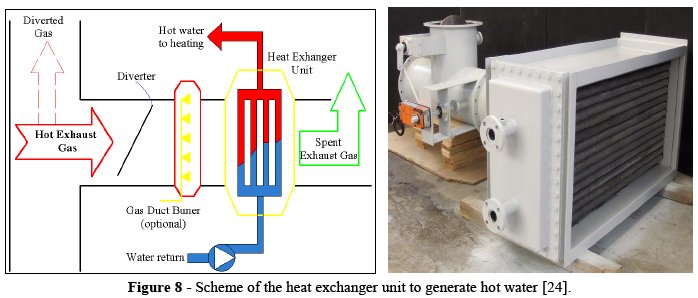
The gas duct burner is optional equipment depending on heating requirements; the diverter is used to control the entrance of the flue gases through the heat exchanger and is related to the exit temperature of the requirements of hot water. The heat exchanger unit has to be designed considering important aspects like selection of tube materials, tube arrangement, pressure drop, fouling factor, fins, heat transfer coefficients, water quality, insulation, duct burner, etc.
There are works performed about the design of compact heat exchangers [17], [18], [19], [20] that use flue gases to generate hot water or steam, they are mostly known as HRSG (heat recovery steam gases). In this project hot water is required to supply the energy for the absorption chiller, for that reason only one heat exchanger (economizer) is going to be evaluated. It is important to know the efficiency of the heat exchanger that the manufacturer gives in the catalogue. Economic and technological aspect must be considered to select the best option for the project.
5. BRIEF DESCRIPTION OF ABSORPTION CHILLERS
Absorption chillers differ from the more prevalent compression chillers in that the cooling effect is driven by heat energy rather than mechanical energy. Absorption chiller can use not only fossil fuel but also the waste thermal energies (hot water, steam and exhaust gas) for cooling, using that waste thermal energy can improve overall efficiency rate and save energy.
Figure 9 shows the absorption chiller cycle. The evaporator allows the refrigerant to evaporate and to be absorbed by the absorbent, a process that extracts heat from the room to be cooled. The combined fluids then go to the generator, which is heated by gas, steam or in this case, by hot water. The refrigerant separates from absorbent and goes to the condenser to be cooled back down to a liquid, while the absorbent return back to the absorber. The cooled refrigerant is released through an expansion valve into the evaporator, and the cycle repeats [3].
Commercial absorption chillers are either lithium bromide-water (LiBr/H2O) or ammonia-water equipment. In the LiBr/H2O system, lithium bromide is the absorber and water is the refrigerant. In the ammonia water system, water is the absorber and ammonia is the refrigerant. Table 4 shows typical values of COP(Cooling Capacity / Heat Input) for different equipment.
The most widespread absorption chillers (driven by hot water or steam) manufactures are: Yazaki Co. (Japan), York Co. (USA), Carrier (USA), Trane (USA), McQuay (USA), Kawazaki (Japan), Sanyo (Japan), Thermax (India). Table 5 shows the main advantages and disadvantages of absorption chillers compared to standard vapor compression chillers.
In this article a Lithium Bromide – Water Absorption Chiller of single effect is used to generate chilled water for air conditioning. Table 6 shows the properties of the absorbent and refrigerant that are used in absorption chillers, as it can be seen they dont have issues with environmental regulations (ODP and GWP).
Figure 10 shows the ODP and GWP values for different refrigerants where water as a refrigerant doesnt have an impact on these parameters. Kyoto and Montreal protocol are the organisms that deal and regulate these parameters.
6. EVALUATION OF THE COOLING AND HEATING CAPACITY
Knowing the available heat, it is possible evaluate the cooling and heating capacity using the equations in Table 7.
Considering the equations of Table 7, it was calculated a constant average flow of natural gas of 3,000 Nm3/h, an efficiency of the heat recovery unit of 75% (worst scenario), a COP of the absorption chiller of 0.6 and a cooling capacity of 20 m2/TR (William [16]). The heating and cooling generation is shown in Table 8.
The results of Table 8 show that with 2,819 kW of available heat it is possible to generate 2,114 kW for heating and 1,268 kW (361 TR) for cooling. The global efficiency of the equipment based on the combustion energy increase 6.91 % when heating is used and 4.14% when cooling is used. The cooling capacity can covers an area of 7,213 m2 considering a cooling capacity for offices of 20 m2/TR.
7. DESCRIPTION OF THE HEAT RECOVERY SYSTEM
To recover the flue gases that are eliminated by the stack, it is necessary to put a derivation duct that takes the flue gas throughout a heat exchanger (HX) commonly called economizer where gives its heat to the water that flows inside the tubes (Wipplinger et al.[17], Ganaphaty [18], Taylor [19], ESCOA [20]); the flue gases need a fan to make circulate the flow through the heat exchanger (pressure drop) and then be eliminated at the atmosphere. The economizer heat the water until reach the necessary temperature to feed the absorption chiller if is cooling or to feed the air handler if is heating.
Figure 11 shows the scheme of the equipment and connections that are needed to accomplish the heat recovery system and it gives an idea of the necessary equipment for the project. With this configuration is possible to control the flow of the flue gases that is required to cover the heating or cooling demand.
The heat exchanger has a purge to eliminate the possible flue gases condensates. The fan is placed after the heat exchanger where the temperature of the flue gases is low (150 °C) and is managed by a driver that controls the temperature of the flue gases and the hot water. It is recommended to install an expansion vessel to avoid over pressure in the line.
8. THERMODYNAMIC ANALYSIS AND DESIGN OF THE HEAT RECOVERY SYSTEM
Once the heating and cooling capacities are obtained, the following step is the thermal analysis of the equipment that is needed for the project; this procedure allows knowing technical data for the selecting and designing of the heat recovery equipment.
Thermoflex Lite V.17 student version is a thermodynamic software for the design and simulation of thermal power plants since 1987. Figure 12 shows the thermal design of the heat recovery system to produce chilled water for air conditioning; from the figure it can see the pressure, temperature, mass flow and electrical consumption of the different equipment. The electric consumption is also considered by the software.
Figure 13 shows more data of an specific equipment, for example the heat transfer to the water side in the economizer is 2,150.5 kW (heating), and for the absorption chiller the cooling load is 1,232.1 kW (350 TR) with a COP of 0.6, the total heat rejection by the cooling tower is 3,286 kW.
The thermal analysis was also modeled in Microsoft Excel® with macros of Visual Basic® using the equations of Table 1, 2 and 7. Table 9 shows the properties of the fluids in each component. For example for the economizer the heat transfer to the flue gas side is 2,818 kW, the heat transfer to the water side is 2,108 kW. The efficiency for the economizer in this case is 74.81% (worst scenario).
Table 10 summarized the energy lost and efficiency of each component of the heat recovery system. Based on the available heat, the overall efficiency of the recovery system is 45% for cooling and 74.81% for heating.
The results show that the flue gases of the industrial furnace can generate 350 TR which represents 1/3 of the total cooling demand of the company. Now the next step is to verify if the project is economically attractive.
9. ECONOMIC ANALYSIS OF THE HEAT RECOVERY SYSTEM
The economic analysis consists in determining the economic feasibility of the heat recovery system taking into account the cooling and heating availability(Ostwald and McLaren [21], Sullivan et al. [22]). The available cooling is evaluated considering conventional refrigeration (vapor compressor chiller) versus absorption chiller. The available heating is evaluated considering a boiler that consumes natural gas to heat the water versus an economizer that uses the flue gases to heat the water for calefaction.
In both cases Investment cost and Operational cost must be evaluated. The costs of most equipment are estimated.
9.1. Cooling investment cost
The cost of the equipment is based on the scheme of Fig. 11; the cost of the coil unit fan is not considered because the unit is already available and is common equipment in both options. Table 11 shows comparative cost of the equipment related to the cooling capacity and COP of the cooling equipment. The comparison is between 1 unit 350 TR absorption system hot water and 1 unit 350 TR conventional systems by electricity. The costs of additional items are estimation over TCE (total cost of equipment) and vary depending of the place of installation. The cost of the equipment also can vary depending on the local market and the availability of the equipment.
The absorption chiller unit is 1.5 times more expensive than conventional chiller. The total investment cost is almost twice more expensive than conventional chiller driven by electricity, the main differences are the extra equipment needed by the absorption chiller (cooling tower, heat exchanger and exhaust gases fan).
9.2. Life cycle and operational cost for cooling
The operative and maintenance cost related to the cooling capacity and COP of the cooling equipment are presented in Table 12.
The operative cost for absorption chiller is 2.5 times less expensive than conventional chiller. The maintenance cost is expensive for conventional chiller due to its components are subjected to high pressure. The O&M (operation and maintenance) and energy costs are estimated values for international markets; therefore these values must be considered carefully in order to have reliable values for the economic analysis.
The savings generated by the heat recovery system for cooling is 54,736 U$D/year, the main difference is the electric energy cost, while the conventional chiller spends 56,813 U$D/year the heat recovery system with the absorption chiller spends only 14,575 U$D/year.
9.3. Heating investment cost
The company uses a boiler to generate hot water for heating. The boiler consumes natural gas as a primary energy. To use the heat recovery system to generate hot water for heating, a heat exchanger is needed. Table 13 summarizes the investment cost as compares the cost of the boiler vs. the cost of the heat recovery system.
As it can be seen in Table 13, the heat exchanger system is almost 2.5 times more expensive than the boiler system due to extra equipment required to generate the hot water like the flue gas fan.
9.4. Life cycle and operational cost for heating
Table 14 evaluates the life cycle and operational cost of both systems considering that for the heating system the boiler uses natural gas while the heat recovery system uses flue gases as a primary energy.
Considering 75 days per year of operation of the heating system, the annual cost for natural gas is 72,216 U$D, which is almost 6 times more expensive than the heat recovery system. The savings in operational costs for the heat recovery system to generate calefaction are 58,291 U$D/year.
9.5. Results of the economic analysis
The summarized results for the economic analysis are shown in Table 15 and take into account the results presented in Table 11 to 14. These values will be used to evaluate the feasibility of the project.
The investment cost for the heat recovery system is 2.5 times more expensive than conventional systems when generating the same cooling and heating capacity.
The annual operational cost for the company to cover the heating and cooling requirements using conventional systems (compressor chiller and boiler) is 161,076 U$D while using the heat recovery system the annual operational cost is 48,049 U$D, which is 3 times cheaper than the conventional operational cost. The annual savings for the heat recovery system is113,027 U$D.
Considering one year of operation (300 days) it is important to notice that 75% of the time is for cooling and 25% is for heating (this can change depending on the place and meteorological weather analysis). The operational savings for cooling are 54,736 U$D/year for 225 days of operation per year. The operational saving for heating is 58,291 U$D/year for only 75 days of operation per year. This scenario is because of the cost of natural gas 10 U$D/MMBtu (0.03412 U$D/kW.h).
Table 16 shows the equation used in this article to evaluate the economic feasibility of the project. The return on the investment (ROI) is an important indicator of the feasibility of the project; it shows the interest that can be obtained on the investment considering the operational cost and the cycle life of the project. The payback period is easy to understand and is widely adopted. The pay back determines how many years it takes to recover the invested capital. The net present value (NPV) compares the present worth of future revenue with initial capital investment at a pre-assigned interest rate [21], [22], [23].
Considering a period of 20 years, which is a typical cycle life of these systems (providing good maintenance and operation), Table 17 shows the results of the economic analysis of the project.
The ROI has a value of 44.07% which is very attractive since a typical accepted value of ROI is 20%, besides the payback period is 2.27 years and considering an interest of 15% the project gives a positive net present value of 451,187 U$D.
Once again, if the project is designed to cover only the cooling demand, which means 54,736 U$D/year of savings and an investment difference of 352,625 (from Table 15), the interest rate of return is just 14%, the payback period is 6.5 years and the net present value is negative (-10,011 U$D) considering an interest of 15%.
For these analysis, parameters like depreciation, taxes and inflation are not considered since these parameters have to be evaluated depending of the fiscal and financial politics of each company and region.
10. RESULTS AND DISCUSSION
Using a validated model developed in Microsoft Excel®, it is possible to get both thermal and economic sensitivity analysis of the project for many cases [24], [25], [26], [27], [28].
10.1. Results of thermal sensitivity analysis
Figure 14 shows the cooling capacity that can be obtained for different flue gases temperature at the stack of the furnace. The small table indicates that the flow of natural gas and the excess air are constant parameters. The exit limit of the flue gas temperature is 150 °C.
10.2. Results of economic sensitivity analysis
As it can be seen from Figure 15, the operation days per year of the new system and the savings obtained from the expenditure into electric energy determine the feasibility of the project.
Considering the values of table 17 and the minimum attractive rate of return of 20% the break even cost of electric energy would be 0.054 U$D/kW.h with at least 150 operation days per year.
11. CONCLUSIONS
Industrial furnaces with flue gases temperature over 250 °C represent an opportunity area for heat recovery systems. Heat recovery systems can be used to generate hot and cool water to cover heating and air conditioning demands. A good evaluation and consideration of the heat availability must be done in order to have reliable values. Applying heat recovery systems in conjunction with industrial equipment requires some thought about overall operation and technical data. The equipment and operational costs must be evaluated carefully because they determine the feasibility of the project.
In this paper it is shown that with data from industrial furnace and considering average values, it is possible to generate 350 TR for air conditioning and also to cover the heating demand all year long, but the period of major maintenance (2 weeks per year approximately) when hot and cool water cannot be provided. The economic analysis shows that with the market cost of the equipment, the actual cost of electricity and the technical data of absorption chillers available in the market compared with conventional chillers, the payback period is 2.32 years and a return on investment of 44% can be obtained.
It is important to mention that the evaluated industrial furnace was not working to the design capacity which means that there is more heat available if the load of iron slabs increase; according to the catalog the industrial furnace can consume 12,000 Nm3/h of natural gas.
The analysis presented shows the importance to realize both thermal and economic analysis of the heat recovery system to consider not only the improvement of the efficiency in the system but also the cost and benefit that can be obtained. With the rising cost of electricity and fossil fuels, maximizing the useful recovery of heat in the industries is more important than ever.
Environment aspects can be considered since the project replaces conventional equipment that work with electricity and fossil fuels. Also absorption chiller technologies use refrigerant that are friendly with the atmosphere. These factors can be a plus for the project and for the image of the company.
12. ACKNOWLEDGEMENT
Thanks to Ternium S.A. and Tecnológico de Monterrey.
13. REFERENCES
[1] B. H.Gebrelassie et al.Economic performance of an absorption cooling system under uncertainty.Applied Thermal Engineering,vol. 29, pp. 3491-3500, 2009.
[2] M. Ishimatsu. Advance Absorption Chillers: Utilization of various heat energies for air conditioning. 1st Europeanpresented at Conference on Polygeneration, 2007. [ Links ]
[3] New Buildings Institute.Absorption Chillers Guideline.Internet:www.newbuildings.org ,1998 [2009]. [ Links ]
[4] ASHRAE 90.1R. Minimum Efficiency. Code Compliance Manual. U.S. DOE. 2000 [ Links ]
[5] P.Kalinowski et al. Application of waste heat powered absorption refrigeration system to the LNG recovery process. International journal of refrigeration, vol. 32, no. 4, pp. 687-694, 2009.
[6] S. Man Lai and H.Wai.Integration of trigeneration system and thermal storage under demand uncertainties.Applied Energy Journal, vol. 87, no. 9, pp. 2868-2880, 2009.
[7] L. Massagués et al. Estudio comparativo de una instalación de trigeneración con microturbina de gas y un sistema convencional con bomba de calor en un complejo hotelero. Universitat Rovirai Virgili, 2004. [ Links ]
[8] A.Arteconi. Distributed generation and trigeneration: Energy saving opportunities in Italian supermarket sector.Applied Thermal Engineering, vol.29(8-9), pp. 1735-1743, 2009.
[9] J.I.Yoon. A study on the advanced performance of an absorption heater/chiller with a solution preheated using waste gas.Applied Thermal Engineering, vol. 23, no. 6, pp. 757-767, 2003.
[10] European Commission for Energy. Energy Savings CHCP plants in the Hotel Sector.Internet: www.newbuildings.org, 2001[2009]. [ Links ]
[11] V. Patnaik.Absorption technology as a sustainable energy solution in the United States. Presented in 1st European Conference Polygeneration.Tarragona (Spain), 16-17 October 2007. [ Links ]
[12] P. Srikhirin et al. A review of absorption refrigeration technologies.Renewable and Sustainable Energy Reviews, vol. 5, no. 4, pp. 343-372, 2001.
[13] K.Goodheart.Low Firing Temperature Absorption Chiller System. Master Degree Thesis of University of Wisconsin, 2000.
[14] H.Kreith, et al. Absorption Chillers and Heat Pumps. CRS Press, 1996 [ Links ]
[15] Y. A. Cengel and M.A.Boles.Thermodynamics an Engineer Approach. Table A.2, Fifth edition, McGraw Hill, 2006.
[16] R.William.Driving Absorption Chillers Using Heat Recovery.ASHRAE Journal, vol. 46, no. 9,pp. S30-S36, 2004.
[17] K.P.M. Wipplinger et al. Stainless steel tube heat exchanger design for waste.Journal of Energy in Southern Africa, vol. 17, no. 2, pp. 47-56, 2006.
[18] V.Ganapathy.Design and Evaluate Finned Tube Bundles, inHydrocarbon Processing, vol. 75, no. 9, pp. 103-112, 1996.
[19] C. Taylor. Measurement of finned-tube heat exchanger performance.Master Thesis, Georgia Institute Technology, 2004. [ Links ]
[20] ESCOA Engineering Manual. Fintube Technologies, Inc.Internet: www.fintubetech.com [2009].
[21] P.F. Ostwald and T.S. McLaren. Cost analysis and estimating for engineering and management. New Jersey: Pearson education Inc., 2004.
[22] W.G. Sullivan et al.Engineering Economy. 12th edition, New Jersey: Pearson education Inc., 2003.
[23] Kawasaki Thermal Engineering. Waste heat energy application for absorption chillers. 3th International District Cooling Conference & Trade Show, Dubai, 2008. [ Links ]
[24] M.J. Moran and H.N. Shapiro. Fundamentos de Termodinámica Técnica.2thedition, Ed. Reverte, 2004.
[25] Waste Heat Recovery. Internet: http://wasteheatrecovery.com/[2014].
[26] F.J.Wang et al.Economic feasibility of waste heat to power conversion.Applied Energy Journal, vol. 84, no. 4, pp. 442-454, 2007.
[27] S.Popli et al.Gas turbine efficiency enhancement using waste heat powered absorption chillers in the oil and gas industry. Applied Thermal Engineering, vol. 50, no. 1, pp. 919-931, 2013.
[28] A. Huicochea. Thermodynamic analysis of a trigeneration system consisting of a micro gas turbine and a double effect absorption chiller. In Energy, vol. 67(16), pp. 548-556, 2014.
NOTAS
[1]Author address: Universidad Privada Boliviana – Centro de Investigaciones Ópticas y Energías (CIOE)

