


Servicios Personalizados
Revista
Articulo
 Español (pdf)
 Articulo en XML
 Referencias del artículo
 Enviar articulo por email
Indicadores
-
 Citado por SciELO
 -
 Accesos
Links relacionados
-
 Similares en
SciELO
Similares en
SciELO
Compartir

 Permalink
Revista Boliviana de Física
versión On-line ISSN 1562-3823
Revista Boliviana de Física v.20 n.20 La Paz 2012
Optical study of the laser beam propagation on Nd:YAG crystal slab for space LIDAR missions
Kosmas Gazeas, George Tzeremes and Errico Armandillo
European Space Agency, ESTEC, Mechatronics and Optics Division Keplerlaan 1, 2200AG, Noordwijk, The Netherlands
Tel: +31 71 5656743, Fax: +31 71 5655430,
E-mail: Kosmas.Gazeas@esa.int, kgaze@physics.auth.gr
SUMMARY
The present paper reports on the development of a simulation and modeling tool which allows to estimate the propagation effects on a laser beam passing through a laser-diode-pumped Nd:YAG slab amplifier. This in-house research work is motivated by current ESA spaceborne LIDAR programs (ADM, Earth Care) as a mean to provide understanding of the LIDAR beam pointing stability as results of thermal and mechanical stresses. A dynamic model has been generated that can simulate the optical characteristics of the laser beam propagation, as a result of the various thermal and mechanical processes occurring inside the laser Pumping Unit and the thermal lensing occurring along the crystal slab. The simulation results and their comparison with actual laboratory tests are being presented and discussed. The model developed is based on the Finite Element Model (FEM) methodology, where the slab as an active element is "broken" down into interdependent segments, each simulated as being heated by an individual LD source. The light beam is propagated along the slab using dynamically varying boundary conditions, to the next so to account for the cumulated thermal and mechanical loads.
Key words: Nd:YAG laser, thermal lensing, LIDARS
INTRODUCTION
LIDARs in space require reliable operation of high power laser transmitters. It is the case for ESA ADM and EarthCare missions where high power UV lasers are being used in an oscillator-multipass amplifier configuration to reach the required energy level and characteristics (Figure 1). ESA space LIDAR programs use both high power Nd:YAG slab, with diode-laser (LD) pumped. In these configurations, thermo-mechanical behavior of the slab can affect seriously the output laser beam characteristics, specifically the most critical variables which can play an important role in the output laser beam are the:
Coldplate temperature (TCP)
Laser Diode physical characteristics and location
Slab geometry
Input beam characteristics
Collimating optics
Operating conditions (air/vacuum, ambient temp.)
To model such processes, it is to be noted that since the number of variables is too large to allow a closed form solution for the thermal lensing of the crystal slab, Finite Element Method (FEM) is proposed and used to compute the combined thermal, mechanical and optical effects.
MOTIVATION OF THIS WORK
energy loss at minimum. Also we will have the ability to predict the outgoing laser beam profile and divergence. This will give direct information for the actual lenses need to be applied before and after the PU, in order to focus the beam and preserve its shape and energy density.
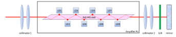
Figure 1. A schematic of the amplifier PU.
Nd:YAG CRYSTAL SLAB GEOMETRY
The crystal slab geometry is shown in Figure 2. A laser beam with a Gaussian profile at 1064 nm enters the crystal parallel along the long axis and bounces 5 times on the top and 5 on the bottom inner surfaces. The other two side surfaces are attached to the cold plates, pumping out the accumulated heat. Boundary conditions are controlled by heat drain from the two cold plates and the energy emitted from the 8 pumping laser diodes at 808 nm.
THERMAL LENSING
The final goal is to achieve fully controlled boundary conditions and direct view of the outgoing laser beam. This way we can predict the necessary modifications needed to preserve the laser energy and amplification efficiency reducing conditions. Each cross section is converted to a refractive index matrix, acting as lens for the laser beam. The number of thermal lenses is a variable parameter in the performance model for fine tuning and resolution control. Laser beam
interacts with thermal lenses, as a normal lens. We assume ray optics (geometrical/linear optics) for the beam propagation and no scatter through diffraction through OPD. Refraction is taken into account via the beams angle of incidence on the thermal lenses (Snell law).
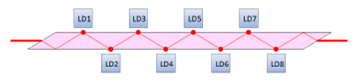
Figure 2. The 1064 nm laser beam is travelling along the Nd:YAG slab, bouncing 10 times on the inner slab surface, while the laser diodes are pumping energy from top and bottom, producing 8 hot spots on the crystal slab. The laser beam enters the crystal from left, exits from the right and its turned backwards with a mirror, causing the beam to enter the slab again, following the same path.
THE DEVELOPED SIMULATION GUI
Our simulations resulted in a graphical user interface (GUI) control panel, where the user can insert all variables necessary for the crystal slab geometry and boundary conditions (TCP and LD boundary temperatures, slab geometry, number of LDs, slabs refractive index, etc), as shown in Figure 3. The incoming beam is assumed to have a Gaussian profile (could be an input variable in a forthcoming version) with a user- defined divergence and the outgoing beam is given for both single and double laser beam pass through the crystal slab. Beam can be shifted up-down-left-right in order to examine the effect of poor optical alignment.
MECHANICAL DEFORMATION – STRESS
Deformation through expansion is taken into account in calculations. This effect does not have any significant direct optical effect. Indirectly, however, it affects conductivity of the crystal slab with the CP, changing boundary conditions. Expansion leads to stress of slab and conductivity variability. This in turn leads in new thermal profile, which can be input as step 1 in our study. Variations of the initial parameters (geometry and environmental effects) as well as the boundary conditions result in a laser beam deformation pattern, according to the input parameters. An example is given in Figure 4.
SIMULATIONS – EXPERIMENTAL TESTS
It is observed that the boundary temperature variations affect drastically the outgoing laser beam shape, resulting in an unfocused and highly divergent non-Gaussian beam. Recent experimental tests demonstrated that small environmental temperature changes as small as 1° C can drastically affect the performance of the PU. This is a result of multiple physical factors being affected simultaneously from temperature (such as the LDs wavelength of operation, the LDs optical to optical efficiency, the absorption profile of the Nd:YAG crystal, the crystal boundary temp. conditions, ASE etc.). Our simulations can resample the existing experimental results and can predict the laser beam profile as a function of the boundary conditions, giving accurate quality results (Figure 5). Moreover, additional results have to be collected for the algorithm calibration. This will be done by in-situ experimental tests performed on a Nd:YAG crystal slab and its amplification performance as a function of temperature perturbations. These final results will provide the actual images required for accurate calibration of our algorithms.

Figure 3. The developed GUI can simulate the thermal profile inside the crystal slab and predict the outgoing laser beam deformation after a single and double pass through the slab. All boundary conditions can be controlled (LD temp., CP temp., laser beam offset, ambient temp., input laser beam profile (assumed Gaussian here), crystal geometry etc).

Figure 4. Small asymmetries of the boundary conditions result in a asymmetric laser beam deformation, visible in both single and double pass through the slab (panels on the right). Note that even 0.5° C difference between the TCP and 1° C between the LD heating cause a significant asymmetry on the outgoing laser beam at the bottom-right panel.

Figure 5. A comparison of actual experimental tests, provided by Selex Galileo (left two panels) with our simulations (right two panels). The results are significantly similar. Precise model calibration and fine tuning of the parameters will allow us to predict the shape of the outgoing beam from the amplifier PU.
CONCLUSIONS
Experimental tests are currently undertaken at ESA/ESTEC establishment, in order to validate the thermal lensing performance model and calibrate/quantify/validate the thermal lensing effect. However, tests already performed by Selex Galileo in Italy show that CP temperature mainly drives the laser beam divergence and focusing ability (shape and profile), while temperature uniformity is the key answer to laser amplification optimization (as well as minimization of the laser beam dimensions). Our results are successful and the developed performance model is a promising tool for studying the thermal lensing effect, caused by a given thermal profile along the Nd:YAG slab.

