


Servicios Personalizados
Revista
Articulo
 Español (pdf)
 Articulo en XML
 Referencias del artículo
 Enviar articulo por email
Indicadores
-
 Citado por SciELO
 -
 Accesos
Links relacionados
-
 Similares en
SciELO
Similares en
SciELO
Compartir

 Permalink
Revista Boliviana de Física
versión On-line ISSN 1562-3823
Revista Boliviana de Física v.20 n.20 La Paz 2012
Remote control and telescope auto-alignment system for multiangle lidar under development at CEILAP, Argentina
Juan V. Pallotta, Pablo Ristori, Lidia Otero, Francisco Gonzalez, Juan Carlos Dworniczak, Raul DElia, Ezequiel Pawelko, Eduardo Quel.
CEILAP (CITEDEF-CONICET), UMI-IFAECI-CNRS 3351
Juan B. de La Salle 4397, B1603ALO Villa Martelli – Buenos Aires, Argentina. E-mail: jpallotta@citedef.gob.ar
Alberto Etchegoyen
ITeDA (CNEA – CONICET - UNSAM)
Av. Gral. Paz 1499 - 1650 San Martín – Buenos Aires, Argentina.
At CEILAP (CITEDEF-CONICET), a multiangle Raman lidar is under development to monitor aerosol extinction in the frame of the CTA (Cherenkov Telescope Array) Project. This is an initiative to build the next generation of ground-based instruments to collect very high energy gamma-ray radiation. It will serve as an open observatory for a wide astrophysics community and will explore the Universe in depth in Very High Energy (> 10 GeV) gamma-rays. The atmospheric conditions are is a major interest for CTA, and this instrument plays a major role measuring the atmospheric optical depth.
The reception system is made by six 40 cm in diameter Newtonian telescopes, totally exposed to the hard environmental condition during the shifts. These working conditions could produce misalignments between laser and telescopes, losing the required overlap. To avoid that, a telescope controlled by a self-alignment system is under development to solve this problem. This is performed by PC software running from the acquisition module which is connected via ethernet to a microcontroller. This paper, describes the self-alignment method and hardware work in progress.
Key words: multiangle lidar, Raman, CTA observatory, aerosols.
INTRODUCTION
The Cherenkov Telescope Array Consortium (CTA) contemplates the design, construction and the operation of two observatories for the detection of gamma-ray produced by extraterrestrial sources at energies range between 1010 eV to 1014 eV. These observatories will be deployed at each hemisphere for full sky-map coverage. Each Observatory will consist of a telescope array sensitive to the atmospheric generated Cherenkov radiation that will improve the performance of the actual detectors. The objectives proposed for CTA will be attained using an array of multiple telescopes distributed over a surface of 1 km2, located at sites with excellent optical and atmospheric conditions at a height of 2000 to 3500 mts above the sea level. The comprehension of the atmospheric conditions during the measurements is extremely important for the CTA Observatory. In fact, the atmosphere acts as the first detector at which the air showers are developed. The array of detectors observe the gamma ray induced cascades by measuring the Cherenkov light produced by their charged particles moving above the speed of light of the surrounding atmosphere. The emitted light is attenuated from the source to the telescope due to molecular, aerosol and cloud extinction. Lidars play a leading role in monitoring of sky conditions, by both detecting the overall cloud coverage and measuring the atmospheric opacity due to aerosol and clouds over the Observatory. The location of this astronomical facility will be selected after a careful study of the preselected zones, regarding the latitude, altitude, the atmospheric conditions, and the available local infrastructure. At the Southern hemisphere, Argentina is one of the candidate countries for the installation of the CTA Observatory. The places proposed are El Leoncito, located in San Juan state and El CASLEO, in Salta.
LIDAR HARDWARE
LIDAR telescope is planned to be mounted on a steerable frame, and moved using two DC servomotors, reading its position by two relative encoders.

Figure 1. A preliminary sketch of the multiangle lidar under construction.
Movements are handled by a microcontroller that communicates with the lidar PC through an ethernet connection. Each LIDAR is equipped with a Nd:Yag laser, that generates laser pulses at 355, 532 and 1064 nm at a repetition rate of 50 Hz and a pulse energy of ~20 mJ @ 355 nm. The backscattered light is collected by six Newtonian telescopes with 40 cm diameter, 1 m focal length. A multiwavelength spectrometer separates the backscattered wavelengths and concentrates the light into several Hamamatsu H6780 photomultipliers. A Licel TR20-160 module is used to digitalize and store the lidar profiles
This lidar has special requirements:
• It has to be able to be operated remotely. The lidar operator may not have an a priori knowledge on lidar techniques.
•Telescopes, mechanics and electronics, will be exposed during nighttime to extreme environmental conditions (wind burst, temperature span, etc.), which could produce lidar misalignments
These are the main reasons that encourage the development of a fully automatic alignment system is to keep the telescopes aligned during the acquisition period.
LIDAR COMUNICATIONS
The lidar system under development has two operational modes: local mode and remote mode. Local mode was developed for maintenance procedures. The presence of a lidar technician is required on site to perform hardware improvements and specific tests. Remote mode was programmed to perform shift operations. In this case the lidar will be remotely operated and monitored from the control center. The lidar computer was designed to communicate with control center server wirelessly via a WiFi link, creating a local lidar network under the TCP/IP protocol.
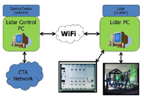
Figure 2. A general schematic layout of the lidar communication system. If remote mode is set, the shifter can monitor and control all the operations.
At the link endpoints, several processes communicate with each other to send/receive control and monitoring messages.
LIDAR SOFTWARE
A more detailed view of the process at each lidar PC can be seen on Figure 3. Each computer works under Linux operating system and all the software was developed in C/C++. A socket-based IPC (Inter Process Communication) was programed to communicate the local with the remote process. To increase their efficiency, each process is totally independent, and communicates to the other via control messages.
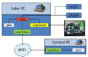
Figure 3. A general diagram about connections in both sides of the lidar system.
A brief description of each process at both sides of the link is described below:
Lidar PC side (client):
adq: Is the main process at the client (lidar) side. It controls the acquisition timing, it communicates with the laser, it triggers the Licel, it sends the acquired new file to the plot process, and, if necessary, to the alignment process.
plot: Waits messages from the adq process, conformed mainly by the new acquired file path and shows it on the display. comToServ: This process handle all the messages from/to the client/server side.
alignment: This process receive the path to the acquired file from adq and process this signal to obtain the alignment parameters to determine the telescope position.
Control PC side (server):
mainServ: Handle the communication between the shifter and the client PC.
plot: Shows the lidar signal from the last saved file.
MICROCONTROLLER-CONTROLLED TELESCOPES
The tilt angle of the telescopes is driven by a set of stepper motors, handled by a RCM2200 Rabbit System microcontroller. This is Z80 family-based high-performance 8 bit microcontroller. It has a built-in Ethernet interface with an integrated TCP/IP stack, making it a good choice for interconnectivity. This interface is used to link the microcontroller with the lidar PC. The instruction set is based on the original Z80 microprocessor, with some additional instructions.
The aims of the Rabbit microcontroller algorithm is to decode the Ethernet information received from the lidar PC alignment process, and to handle the signals to correct the stepper motor drivers. The message from the lidar PC to the Rabbit microcontroller has 3 parameters: motor to be controlled, direction and number of steps. Therefore, the firmware of the Rabbit microcontroller is a dummy terminal that only receives message and drives the motor. After that, it sends an acknowledge message back to the alignment process.
ALIGNMENT ALGORITHM
The alignment algorithm is a cooperative procedure between the adq and the alignment processes, both running on the lidar PC, and a firmware recorded in the Rabbit microcontroller.
When the alignment mode is set at the adq process, each path of the acquired file is sent to alignment. Moreover, after saving a new file at the lidar PC, this file is transferred to the control PC for a backup. A summarized procedure flowchart can be seen on Figure 5.
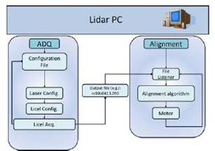
Figure 4. Communication Diagram between the acquisition and the alignment processes. Both are fully independent, and they communicate via the IPC socket, implemented under C/C++.
The aim of the alignment algorithm is to quantify the alignment state of the recently acquired file and to save it with its tilt position in a table. After that, alignment tilts the telescope to a new position and sends an acknowledge message to acq, to trigger new acquisition.
The alignment state quantification is obtained by accumulating the lidar signal over certain range, as it seen on the next figure:
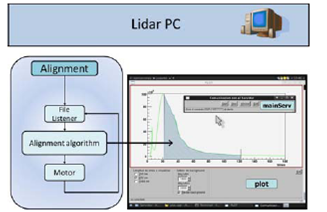
Figure 5. After finishing the scanning process, the microcontroller sets the telescope position to the one at wich the maximum value was attained. This procedure tends to increase the lidar signal in a wide dynamic range.
FIRST RESULTS
This algorithm was successfully tested, comparing the vertical lidar signals obtained with the ones obtained by the MWRL lidar at CEILAP (CITEDEF-CONICET). The test was done for a vertical fixed position, as can be seen on Figure 4.
The CEILAPs telescope was manually aligned to provide the reference signal. The tested telescope was left intentionally misaligned to test the optimization algorithm.
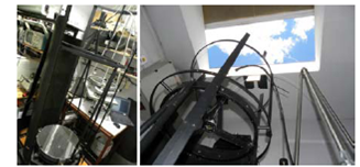
Figure 4. Picture of the setup of lidar intercomparison.
After turning on the alignment mode, the algorithm exhibited good results, approaching the telescope's signal under test to the reference lidar signal. The next figure shows the lidar signals after the alignment process.
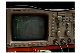
Figure 5. Picture of the lidar signals intercomparison after alignment algorithm success.
The differences seen on the last figure are due to the different distance to the laser source of the systems. Figure 5 shows the long range agreement of the signals.
CONCLUSIONS
The system is ready to be tested in a slant path fixed angle. The lidar is actually being installed inside a container to perform this new test. A new enhanced version of the controlled telescope actuators is under construction. First measurements indicate that it will be possible to achieve the expected auto-optimizations goals during the scanning procedure. The new software for a multiangle lidar prototype is fully operational.
ACKNOWLEDGMENTS
Authors wish to thank JICA, ANCyPT, the CITEFA main workshops technicians and José Luis Luque from the CEILAP workshop for their support on this development.
REFERENCES
1.- Otero, L. A. et al. (2004). First Aerosol Measurements with a Multiwavelength LIDAR System at Buenos Aires, Argentina Proceedings of the Conference of the ILRC2004. [ Links ]
2.- http://www.digi.com/ http://www.cta-observatory.com/, http://astrum.frm.utn.edu.ar/CTA-Argentina/ Licel programing examples and documentation: http://www.licel.com/soft_tcp.html [ Links ]

