


 Inglés (pdf)
 Articulo en XML
 Referencias del artículo
 Enviar articulo por email
 Citado por SciELO
  Similares en
SciELO
Similares en
SciELO 
 Permalink
1 Introduction
The environmental crisis due to climate change and the energy crisis due to the depletion of fossil hydrocarbons force humanity to increasingly develop the use of renewable energies. In all countries, strong investments are being made to generate more and more energy from solar energy and wind. The intention is to cover an increasingly larger proportion of the energy we require for the domestic, commercial and industrial activities we carry out. However, the use of renewable energies is not so simple. Among the different limitations that arise, one of the most important is the intermittency of the availability of renewable energies; Solar energy is available about 8 to 10 h a day, depending on location, and wind energy is very intermittent and unpredictable. This situation greatly complicates meeting the daily power demand for energy, particularly electrical energy, from these sources.
One way to resolve the discrepancy between renewable energy supply and energy demand is to store renewable energy generated during times of high availability and then use it when it cannot be generated to meet demand. Unfortunately, energy storage is not as simple as it seems, especially if we consider that what must be stored is exergy, that is, the usable part of the energy. The term exergy was first introduced by Z. Rant in 1956 (Rant, 1956) from the Greek terms ex (external) and ergos (work) and refers to the maximum amount of work that a system can deliver in a defined environment. It results from the combination of the first and second laws of thermodynamics. This quantity can be transferred from one system to another, but it is only conserved if the transfer process is done reversibly. By definition, a reversible process is an ideal process that we can only imagine; in practical reality, reversible processes do not occur. Therefore, every time an observable transformation occurs, exergy transfers occur, and part of this exergy is lost in the process. In fact, when we talk about energy consumption or energy efficiency, we are referring, sometimes unknowingly, to exergy consumption. When we consume exergy, we destroy it, and it is dissipated into the environment in the form of heat.
Therefore, when it comes to designing energy storage systems, what is intended is to store exergy. In the case of renewable energies, we can synthesize the processes into exergy capture (solar or wind), exergy storage, conservation of stored exergy, recovery of stored exergy and conversion of exergy to a usable form (generally electrical energy). In each of these stages, exergy losses are generated, which depend on the way in which the exergy is transferred and stored. In practice exergy can be stored mainly in the form of (Smdani et al., 2022):
Internal exergy (Availability): when exergy is stored through changes in the thermodynamic state of the system (pressure and temperature) that do not involve a chemical reaction; thermal masses (sensible heat and latent heat), compressed gases, etc.
Potential exergy: when exergy is stored in the form of a gain in potential energy of a mass: hydroelectric plants, gravitational batteries, etc.
Kinetic exergy: When exergy is stored in the form of kinetic energy, usually inertial systems.
Chemical exergy: When exergy is stored through a chemical reaction, as is the case with batteries of all types, hydrogen and other forms.
Electrical exergy: when electrical energy is directly stored, this is the case of supercapacitors (SCs) and superconducting materials that store magnetic energy (SMES)
Currently, a lot of research is being carried out on different storage systems with the aim of improving their efficiency, reducing costs and adapting the systems to the needs in terms of storage capacity, control of the generated power and integration with traditional electrical energy generation systems.
The storage of exergy in the form of thermal energy is one of the alternatives used in concentrated solar thermal power systems (CSP) such as the concentration tower system (Solar Power Tower) and the parabolic mirror system (Parabolic Through) and others similar. In these cases, solar energy is collected in the form of thermal energy initially through a hot thermal fluid, this thermal energy is stored in thermal masses that store heat in the form of sensible heat or latent heat, then this thermal energy is recovered to operate some power cycle and generate electrical energy. Although thermal exergy storage systems offer some advantages over other systems, such as relative ease of building autonomous systems, not depending on the topography and location of the land and other advantages, the biggest problem is the low efficiency in the exergy charge-discharge cycle that results in a relatively high cost. The efficiency of these systems ranges between 30 and 50% (Smdani et al., 2022) . The inefficiency of these systems is largely due to exergy losses occur in various ways, and it is not as easy to identify them, as is the case with other storage systems. To determine these losses, it is absolutely necessary to perform an exergy flow analysis in these systems, as suggested and evidenced by several authors (Bindra et al., 2013;Jegadheeswaran et al., 2010;Zalba et al., 2003) .
In this work, exergy storage in latent heat storage systems is considered, with the use of phase change materials (Phase Change Materials or PCMs). Irreversibilities are analyzed due to the characteristics of the PCMs and the internal and external conditions under which they operate. A qualitative approach is also proposed to select the best PCM options for certain applications.
2 Characteristics of latent heat storage systems.
The storage of latent thermal energy occurs when a chemical substance undergoes a phase transition without changes in the chemical composition, that is, without a chemical reaction. For this, the so-called phase change materials or PCMs are used. The most used phase transition for heat storage is the transition from solid to liquid, for the charging process, and the transition from liquid to solid for the discharge process. For cold storage, the process is reversed for loading and unloading. The essential advantage of this type of transition is that the volume change of the material is small when it goes from solid to liquid and vice versa, even though the enthalpy of this transition is relatively small compared to a liquid/vapor transition.
In a PCM intended to store heat, the charging process is generally carried out at constant pressure and a heat source is used, which can be a heat transfer fluid that transfers thermal energy to the PCM or an external heat source, which is at a temperature higher than de fusion temperature of the PCM. We can consider the PCM as a closed system and apply the first principle of thermodynamics to calculate the heat exchange and its relationship with the change of state of the system, using the following equations:

In this equation, the term 𝛿W refers to the work exchanged during the process. In the case of PCM fusion, the work exchanged would only be associated with the expansion of the material that is produced by its fusion. In general, the solid phase has a smaller specific volume than the liquid phase. Therefore, we can replace this term with 𝛿W = -PdV:

Rearranging the terms we reveal the heat exchanged in the process, and, since the process is at constant pressure, it is shown that the heat exchanged is equal to the enthalpy change of the system:

In general, when heating a solid, the liquid phase appears at a temperature slightly higher than the specific melting temperature of the material, this phenomenon is called overheating, and when cooling the liquid material, the solid phase appears at a temperature lower than the melting temperature of the material, this phenomenon is called undercooling of the material. If we graph the fusion and solidification process of a phase change material on a temperature vs enthalpy diagram, we will have something like what Figure 1 schematically. Formally, the melting temperature (Tm) is the average value of the temperatures 𝑇𝑓𝑢𝑠 and 𝑇𝑠𝑜𝑙 that appear in this figure.
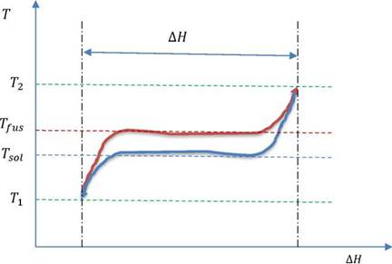
Figure 1. Graphic representation of a charge and discharge cycle of a phase change material in the charging stage (red line) and the discharge stage (blue line).
In practical terms we can estimate the heat exchanged during the loading process from the specific thermal capacities of the solid phase (𝑐𝑝.𝑠) and the liquid phase (𝑐𝑝.𝑙), the specific enthalpy of fusion (Δℎ𝑓) of the material and the temperatures at which the fusion and solidification processes of the material occur, with the following equation

From equation 4, we see that part of the heat stored in a PCM is sensible heat and part is latent heat. In practice, the heat source temperature (𝑇𝑐) during the charging process has to be higher than 𝑇𝑐>𝑇2 the maximum cycle temperature to guarantee heat transfer in a reasonable time, and, similarly, the cold source temperature (𝑇𝑓) at which the heat is discharged in the discharge process must be lower 𝑇𝑓 < 𝑇1 than the minimum temperature of the cycle, for the same purpose.
When analyzing the efficiency of PCMs in terms of thermal energy conservation, the efficiency or performance criterion (𝜂) is quite simple and simply considers the heat that is incorporated into the PCM in the charging process (Qc), and the heat that is recovered in the discharge (Qd)(Bejan, 2016) .
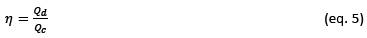
The performance in terms of energy simply expresses the eventual losses of thermal energy that occur due to heat flows towards the environment during the heat storage time before discharge, or during the charging and discharging process, in general these losses are small.
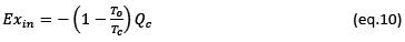
In terms of exergy analysis, the efficiency of an exergy thermal storage system (𝜓) is established in terms of the exergy delivered during the charging process (Exc) from some heat source (eventually a heat transfer fluid) in relation to the exergy recovered during the discharge process (Exd). The second law efficiency or exergy efficiency can be expressed by the following equation:
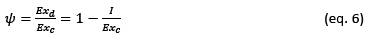
In this equation I is the irreversibility of the process which is defined as the exergy lost during a process. In mathematical expression, irreversibility in a process is the difference in the real work exchanged and the reversible work that could be exchanged. It can also be shown that there is a direct relationship with the change in entropy of the universe:

This last expression is the well-known Gouy-Stodola equation, published in 1889 (Gouy, 1889). This expression shows a direct relationship between the irreversibilities of a process and the generation of entropy in the universe, therefore, reducing the irreversibilities in a process is equivalent to reducing its entropy's creation in the universe. Another consequence of this equation is that the only way to eliminate the irreversibilities of a process is to make the process be carried out reversibly. In practice, a reversible process would be an infinitely slow process, therefore it is impossible to achieve 100% efficiency based on the second law efficiency criterion, but we can get closer to it as far as possible.
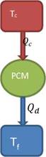
3 Intrinsic irreversibilities of a latent heat storage system
Figure 1 shows the cyclical charging and discharging process of a latent heat heating system or PCMs. It is important to note that this process has intrinsic irreversibilities specifically associated with the behavior of the phase change material. To analyze the behavior of these irreversibilities we will start from the assumption that this phase change material is charged from a heat source at temperature Tc and is discharged towards another heat source at temperature Tf. We will assume that these heat sources are ideal, and their temperatures remain constant (see Figure 2). We assume that the temperature of both sources is above the ambient temperature (Tc > Tf > To) and that all the heat delivered by the hot source is then recovered by the cold source, and there is no heat losses due to the accumulation time of thermal energy. In this way we concentrate on the exergy losses due only to the charging and discharging process since there are no heat losses to the environment, that is, Qc = -Qd.
The irreversibility of the process can be calculated with the Gouy-Stodola equation using the following expression:

Integrating this equation over an entire charge and discharge cycle of the PCM, the entropy change associated with the PCM would be zero, therefore the irreversibility of the process would be given by:

The second law efficiency of the process can be calculated using equation 6 and considering that the exergy received by the PCM is equal to:
Replacing these expressions in equation 6 we obtain:
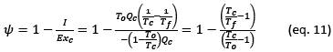
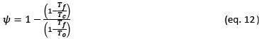
In this last equation we can see that the efficiency of the PCM depends essentially on the temperatures of the hot source and the cold source, more precisely on the difference between these temperatures ΔT = Tc - Tf, when this difference tends to zero, the efficiency tends to 1. This difference of Temperature is conditioned by the degree of superheating and subcooling that the PCM requires to carry out the fusion solidification cycle and the temperature gradient necessary to guarantee the minimum heat flow required according to the power demand of the system. The greater the superheating and subcooling and the greater the thermal gradient, the lower the PCM efficiency will be.
In a similar way, we can demonstrate the second law efficiency for a PCM that stores cold, that is, it has a melting temperature that is below the ambient temperature (To > Tc > Tf).
The melting temperature of the PCM (Tm) can serve as a reference to express the values of Tc and Tf approximately we can assume that:
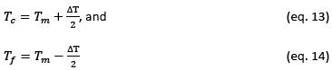
Assuming these values, the second law efficiency can be graphically represented for a PCM that stores heat or cold, as a function of its fusion temperature and in an environment that is at 25 °C. The graphic representation of the intrinsic second law efficiency of a PCM to store cold and heat is reflected in Figure 3, it is clearly seen that when the melting temperature approaches room temperature, the second law efficiency decreases drastically until become null. Consequently, when the melting temperature of the PCM moves away from the ambient temperature, the thermal exergy storage efficiency of the PCM increases. The effect of the temperature difference between the cold source and the hot source on the efficiency is greater when the melting temperature is closer to the ambient temperature, at melting temperatures much above or very below the ambient temperature, the effect of this difference is much smaller.
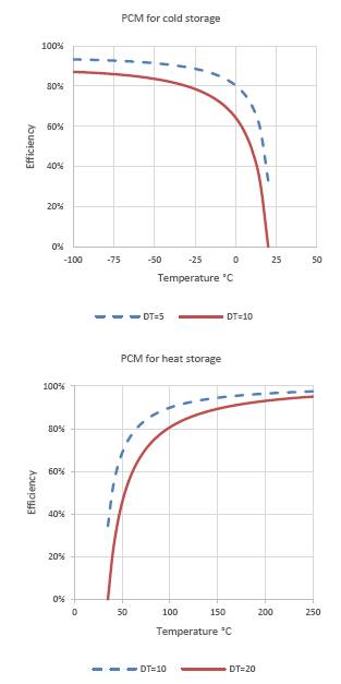
Figure 3. Second law efficiency of a PCM that stores cold (left) and one that stores heat (right) for an ambient temperature of T0 = 25°C and different values of ΔT, 5 and 10°C for cold storage (above) and 10 and 20°C for storage of heat (below).
The analysis of these results shows us that the efficiency of the PCM will be greater than 86% if its fusion temperature is about 100°C above or below the ambient temperature and that this will be zero if we are very close to the ambient temperature. In practice it has been established that as the melting temperature of the PCM increases, the exergetic efficiency also increases, a study carried out by Mahfuz (Mahfuz et al., 2014) shows that in applications to solar energy CSP systems, a PCM with a melting temperature of 190°C has an exergetic efficiency of 15% and another with a melting temperature of 250°C has a 86% efficiency. If the PCM operates at temperatures close to ambient temperature, it will be essential to reduce the temperature difference between the hot source and the cold source to the minimum possible. Therefore, if the purpose of thermal storage is intended to generate work with some power cycle, as is the case with CPS or CPT systems, it is important to carry out the storage at the highest possible temperature, within the stability ranges of the heat transport fluids.
In practice, the charging and discharging power or heat flow is an important parameter as it determines the time and ease with which a PCM can be charged or discharged. To achieve higher powers there is a tendency to simply increase the temperature difference. between heat sources (Medrano et al., 2009) , but as the results above show, this option significantly reduces the second law efficiency of the PCM. The correct thing is to increase the overall heat transfer coefficient (U) and/or the contact surface. The same conclusions are reached when sensitive thermal energy storage systems are analyzed (Dincer & Rosen, 2007;Rosen & Dincer, 2003) .
Superheating and subcooling is an intrinsic characteristic of each substance that is used as PCM, the difference between the melting temperature Tfus and the solidification temperature Tsol can vary from a few degrees °C to tens of degrees, depending on the PCM, these asymmetries occur in almost all PCMs (Gomez, 2011;Jin et al., 2015;Kenisarin, 2010) . In this case it is necessary to reduce this temperature difference, and it is possible to achieve this with additives that facilitate nucleation centers in the PCM crystallization process, however it is still necessary to carry out research on this aspect. An interesting and promising technique is the formation of PCM infiltrated in a graphite foam, in this way the heat transfer is significantly increased and the overheating / overcooling of the PCM is reduced (Lan et al., 2020).
4 Analysis of the use of PCMs in solar thermal plants
An important application of thermal energy storage systems are solar thermal plants, particularly CSP tower concentration plants, or plants that use parabolic mirrors that concentrate radiation in a tube with a fluid that recovers the energy, CPT type. In this type of systems, daily storage of exergy in the form of thermal energy is required. In an autonomous system that provides electrical energy for domestic, commercial and other uses, the effective hours of solar energy collection are about 8 to 10 hours a day. Therefore, it is necessary to store between 50-55% of the exergy received during the day to recover it during the hours of the night when there is no solar radiation.
In CSP systems, solar radiation is initially reflected by a system of mirrors, called a solar field, towards a receiver located at the top of a solar tower. The radiation is absorbed in the receiver and transferred to a high temperature heat transport fluid. The thermal energy collected by the fluid is stored or transferred to a power cycle that transforms the thermal energy into electrical energy. In the case of CSP systems, the configuration of the thermal energy storage system can be done in several ways. When energy is stored in a molten salt the storage can be direct, when the molten salt itself recovers heat at the receiver, or indirect when heat is stored in a heat storage system like with PCMs (see Figure 4).
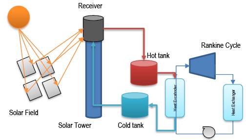
Figure 4. Schematic of a CSP system with direct heat storage of solar energy in a molten salt system.
Most of these types of systems that are in operation in the world use molten salts and store heat in the form of sensible heat, the storage capacity of these salts is between 2.5 - 2.9 MJ m -3 K -1 (Alva et al., 2018). For a system like Cerro Dominador located in the town of María, Chile, about 45,000 t (23,700 m 3) of molten salts are required to store thermal energy (Cerro Dominador Salt Smelting Process Started - Mining Report I El Portal of Mining in Chile , nd) . The salt is heated to about 540°C in the loading process and cooled to about 290°C in the discharge process, therefore the sensible heat storage capacity is about 700 MJ m -3 . This value is comparable to the values obtained in latent heat storage systems for PCM with fusion temperatures around 300 - 450 °C, whose values are between 700 and 2,400 MJ m -3 (Alva et al., 2018;Kenisarin, 2010) , therefore in terms of storage volume between sensible heat and latent heat systems, we could say that PCMs provide a capacity that is double that of sensible heat systems. In practical terms the advantage is significant. Therefore, it is important to analyze whether PCMs would provide any advantage in terms of exergetic efficiency in this type of storage systems.
In a CSP system the exergy flow comes from the solar radiation that hits the mirror field, it is reflected towards the receiver where the energy is recovered through a thermal fluid (molten salt in the case of direct systems), the exergy is transferred to the thermal storage system and finally transferred to the power generation cycle. The global exergetic efficiency can be decomposed into these four stages so that the global efficiency would be given by (Xu et al., 2011):

4.1 Analysis of the efficiency of the solar field and the receiver of the solar tower
The field efficiency (𝜓𝑐𝑎𝑚𝑝𝑜) depends on the spatial arrangement of the mirror field around the tower, the reflectivity of the mirrors, interference and attenuation factors, interception factors and the fraction of exergy contained in solar radiation, it varies with the position of the sun during the day. Something important about this factor is that it does not depend on the working conditions of the fluids and can be estimated thanks to computer models available such as the SolarPILOT program. (US DEpartment of Energy, n.d.). Once the system is built and established, there is not much that can be done to improve efficiency, generally this efficiency is in the range of 45-65%.
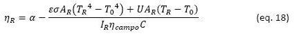
The efficiency of the receiver (𝜓𝑅) depends strongly on the temperature conditions at which heat is transferred from the receiver to the thermal fluid and the exergy content in that heat flow. To understand this element, it is necessary to start from an energy balance of the radiant heat received by the system:

In equation 16,

This performance can be estimated from the following equation that considers the absorbance of the receiver (𝛼), the surface of the receiver (AR), the direct radiation intensity DNI (IR), the radiation concentration factor (C), the temperature of the receiver surface (TR), an overall heat transfer coefficient by conduction and convection (U):
The exergy flow associated with the transferred heat flow
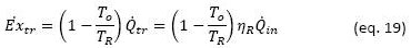
The exergy flow incident on the receiver is equivalent to the radiant heat captured multiplied by the Petela factor (𝜓P), which reflects the fraction of exergy associated with a flow of solar radiation (Petela, 1964):

Assuming the sun's temperature 𝑇𝑠 = 6000 K, 𝜓𝑃= 0.934. And the second law efficiency would be given by:
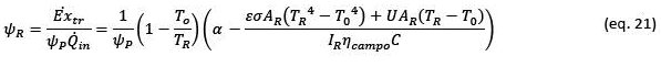
In Figure 5 exergetic efficiency of the receiver are presented as a function of the temperature of the receiver and different intensities of solar radiation, considering values related to the cerro Dominador solar tower. In this graph we see that the point of highest efficiency in terms of exergy capture of the receiver depends on the temperature of the receiver and the intensity of solar radiation, the higher the intensity, the higher the optimal temperature. For the intensities considered (600, 800 and 1,000 W m-2), the optimal temperatures are 720 °C, 780 °C and 820 °C, respectively. As the intensity of radiation varies throughout the day, the optimal temperatures for exergy capture will also vary. In this same graph we also see that the maximum efficiencies achievable in this stage are between 57% and 62%, that is, a good part of the exergy of solar radiation is already lost in this stage.
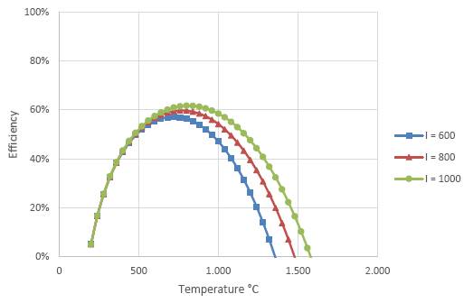
Figure 5. Exergetic efficiency of the receiver according to equation 21 for an ambient temperature of 25 °C and for different intensities of solar radiation in W m-2.
If we maximize equation 21 as a function of TR, we will obtain the optimal working temperature of the receiver to achieve the highest possible exergy flux. The optimal working temperature of the receiver depends on several specific characteristics of the heliostat field, the receiver operation temperature and characteristics, and the concentration factor. Figure 6 shows the optimal working temperatures of the receiver for the conditions of the Cerro Dominador project, Chile, for different hours of the day and for different season of the year, according to the data and characteristics of the heliostat field published in (Cuevas, 2020).
In Figure 6 we see that the optimal temperature depends on the radiation intensity that varies both throughout the day and from one season to another. At the time of maximum daily radiation, the optimal temperature in the month of November is 779 °C and in the month of June it is 732°C. On this figure we see some anomalous values of efficiency close to 6 h in November and to 8 h in June, this is due to some shadow by mountains near the field.
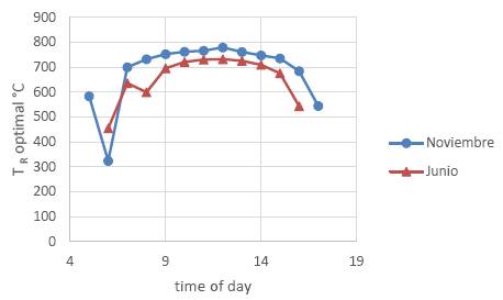
Figure 6. Optimum tower receiver surface temperature under the conditions of the Cerro Dominador project in Chile for a typical day in November (•) and for a typical day in June (▲). The ambient temperature is assumed 20°C.
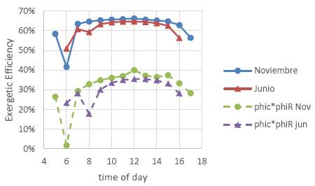
Figure 7 shows a graph with the exegetical efficiency of the receiver as a function of the time of day, according to equation 21, for an average day in the month of June and the month of November, which correspond to the months of lower and higher radiation intensity, respectively. The average receiver efficiency in June was 61% and in November was 62%. In this same graph we observe the combined efficiency of the mirror field and the receiver, the average values are 30.5% for June and 31.6% for November, this implies that about 69% of the exergy available in solar radiation is lost in these first two stages of the CSP system, under optimal conditions. If the operating conditions of the receiver are not optimal, even more exergy would be lost in the early stages.
4.2 Analysis of the efficiency of the thermal storage system and the power cycle
As shown in point 4.1, after the first two stages of a CSP system, only 31% of the radiant exergy captured by the solar field mirror system is transferred to the thermal fluid to be stored and then transferred to the power cycle that will ultimately convert this heat flow into electrical exergy. To analyze the exergetic efficiency of this second stage, it is convenient to consider the receiver as a heat source that works at the temperature of the receiver (TR), the heat is transferred to the thermal fluid, which can be a molten salt or another type of thermal fluid. To simplify the present analysis, we will not consider the exergy losses associated with losses due to the friction of flows in pipes and other devices and the eventual heat losses to the environment, which, although significant, are not losses associated with the process' conditions and ways to reduce them are well known.
The challenge is to find the best thermal exergy storage configuration that reduce the losses associated with the heat storage process and the power cycle used to transform thermal exergy into mechanical exergy that can be used to generate electrical energy.
If PCMs are used as a thermal storage system, the important parameters are: the melting temperature of the PCM to be used and the superheating and subcooling temperatures. As previously shown, it is essential that the difference in maximum and minimum temperature of the PCM charge and discharge cycle is as small as possible. Ideally, this difference should be ΔT ≤ 20°C, however, some PCMs have cycles that require overheating or subcooling. (ΔT) in a range of 30 to 70°C. Unfortunately, in the literature on PCM for high temperature systems, this value is not often published.
Bejan (Bejan , 2016) and other authors propose an optimal temperature for the melting temperature of the PCM that stores exergy. Their analysis starts from a scenario in which the PCM receives heat from a high temperature fluid that comes into contact with the PCM at a temperature Tin and transfers heat to a PCM with a fusion temperature Tm, in an environment that is at a temperature To , to then dissipate the residual energy of the fluid to the environment. In this scenario it can be shown that the optimal fusion temperature of the PCM (Tm, opt.)would be given by:

In the case of Cerro Dominador, the average optimal operating temperature of the receiver is about 990 K. We can assume that the hot fluid that recovers the thermal energy from the receiver can be heated up to about 970 K and this would be the inlet temperature to store the thermal energy in the PCM(s). If we assume an ambient temperature of 293 K, the optimal melting temperature of the PCM would be about 533 K (260°C). However, the real scenario in which a PCM would operate in a CSP system is different from the scenario proposed by Bejan since the hot fluid does not necessarily discharge the remaining thermal energy to the environment but conserves it to return to the receiver and heat up again, or eventually, this fluid could transform or transfer its remaining exergy through a power cycle into usable work. To determine the optimal operating conditions of a thermal storage system with PCMs, it is necessary to previously establish a scenario or concept of the system.
The generation of entropy in processes in which heat is exchanged is directly associated with the temperature differences between the systems that exchange heat; therefore, the strategy to reduce the generation of entropy consists, essentially, on reducing the temperature differences between systems that exchange heat.
A simple and graphic way to analyze exergy losses or irreversibilities in heat transfer processes is through enthalpy diagrams versus the Carnot coefficient. To explain this, we start from the reversible work (𝛿Wrev) associated with a heat flow (𝛿Q) exchanged by a system, which is given by the following equation:
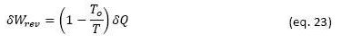
Where To is the temperature of the environment and T is the temperature of the system that exchanges heat. If the process occurs at constant pressure, we can replace 𝛿Q = dH, as is generally the case in CSP systems. Therefore, reversible work exchanged in a process can be calculated by:
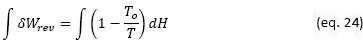
This integral represents the surface under the curve that describes the transformation process in an Enthalpy (H) versus diagram
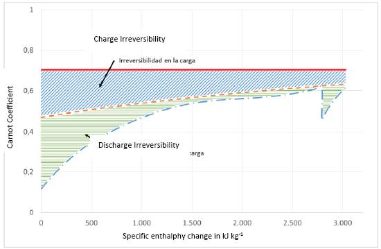
Figure 8. Graphic representation of the irreversibilities in the charging and discharging process of a sensible heat thermal storage system (solar salt). Charging is carried out from a heat source at 990 K, heat is transferred to a flow of solar salt that is heated from 563 K to 813 K. In the discharge the solar salt transfers heat to water from 337 K to 773 K at a pressure of 300 bar, typical of a Rankine cycle with reheat used to generate mechanical work in a CSP system. The solid line represents the heat source process, the dotted line represents the solar salt process (charging and discharging), and the dot segment line represents the water heating process.
In Figure 8, the area below the filled line (red), represents the exergy transferred by the external heat source, appears as a simple horizontal line since its temperature remains constant. The dotted line represents the charge and discharge process of solar salt that changes its temperature from 563 to 813 K, the area under this curve also represents the exergy stored in the charge (from left to right) and in the discharge process. The difference between these two areas (light blue hatching) represents the irreversibility of the charging process. At discharge, heat is transferred to a flow of water that is heated from 337 to 773 K at a constant pressure of 300 bar which is transformed into steam in the boiler, just before entering the turbine. The difference in the area under these two curves represents the irreversibility of the solar salt discharge process.
In the same Figure 8 we can analyze the impact that the flow and inlet and outlet temperatures have in terms of the inlet and outlet exergy of the solar salt. Although increasing the salt flow and increasing the inlet and outlet temperatures would reduce the exergy loss in the charging process, the losses would increase in the discharge process by the same proportion. That is, the global exergy loss ultimately depends only on the difference between the area of the curve that describes the exergy associated to the heat source process and the area corresponding to the exergy captured by the water heating process to generate steam for the Rankine cycle. The only option to reduce exergy losses in this process would be to raise the inlet and outlet temperatures in the water heating stage for the Rankine cycle. However, there are practical limits to the maximum temperature and maximum steam pressure that can be used in a real turbine, the maximum temperature range being between 570 - 620 °C and the maximum pressure range between 250 - 300 bar (Ohji & Haraguchi, 2017) . Furthermore, the maximum steam temperature at the turbine inlet must be lower than the maximum operating temperature of the solar salt, which is 540 - 560 °C.
From the analysis of Figure 8 we can conclude, qualitatively, the following: the irreversibility of the charging and discharging process essentially depends on the temperature of the heat source and the temperatures of water heating stage of the power cycle. Under the process conditions shown in the figure, the second law efficiency of the loading and unloading process would be 67.8%. The exergy transferred to the steam is converted into mechanical work with an efficiency of 93.22% through the Rankine cycle, therefore the overall efficiency of the CSP system, applying equation 15, would be 19.97%, considering the intensity of solar radiation in November. This value is similar to that calculated by other authors in previous analysis works (Cuevas, 2020) . The loss of exergy could be reduced by increasing the temperature of the steam at the exit of the heating process, but the thermal storage in the solar salt prevents increasing this temperature above the maximum operating temperature of the solar salt since it decomposes at temperatures higher than 600°C.
Consequently, to improve efficiency in the storage stages and the power cycle, a configuration is necessary that allows heat transfers to be achieved at higher temperatures and reduce temperature differences between the elements between which energy is exchanged in the form of heat.
4.3 Proposal to incorporate PCMs as a thermal storage system in a system
Phase change materials can store larger amounts of thermal energy in a smaller volume, relative to sensible heat systems, on the other hand, the temperature change to achieve this storage is smaller. These characteristics contribute to reducing exergy losses in storage processes. However, it also has disadvantages, among them is that these materials work encapsulated and cannot flow, therefore it is necessary to implement an indirect heat storage system, that is, a fluid is required that allows to recover heat from the receiver of the tower to then transfer it to the PCM, and another fluid is also necessary to recover the exergy stored in the PCM. These additional heat transfers result in exergy losses in the process. On the other hand, as explained previously, PCMs can have superheating and subcooling temperatures that require high temperature ranges to carry out the fusion and solidificaron cycle.
The fluid used to recover heat from the tower receiver must withstand high temperatures, around 720°C to recover heat with the minimum possible temperature difference in relation to the receiver. This fluid must transfer the recovered thermal energy to the PCMs and then be able to recover it. Considering these limitations and requirements of the PCMs, an interesting alternative would be to use a gaseous fluid such as CO2 as a thermal fluid and take advantage of a combination of Bryton and Rankine cycles to convert the exergy recovered in the receiver into mechanical work and, at the same time, store thermal exergy in the PCMs.
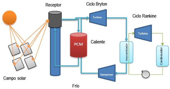
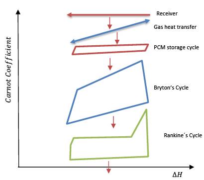
Figure 9. Scheme of the proposal to use PCMs in thermal energy storage in a CSP system. The light blue arrows reflect gas flows (CO2) and the light green arrows reflect water flows.
The system would operate as follows: the compressed CO2 would enter the receiver at a temperature slightly higher than the outlet temperature of the Bryton cycle compressor and would be heated to the maximum possible temperature considering the optimal receiver temperature shown in Figure 6. At the outlet of the receiver, part of the gas flow (40-50%) would be diverted directly to the Bryton cycle gas turbine to generate mechanical power in the combined Bryton /Rankine cycle. The rest of the gas flow would be diverted to a PCM tank where a gas/solid heat exchange would occur to store the thermal energy at high temperature. The flow of this derivation should be as high as possible to reduce the temperature drop at the outlet of the PCMs tank, in this way the exergy loss in the loading of the PCMs would be reduced and PCMs could be used at high temperatures, between 600-650°C. During hours without sun, the flow of gases leaving the compressor would be heated in the loaded PCMs to a temperature close to 580-630°C, before entering the Bryton cycle turbine, in this way the combined cycle can operate during hours without sun to provide the electricity demanded during these hours. The system is shown schematically in the Carnot Coefficient vs ΔH diagram in Figure 10
To reduce exergy losses in these processes, it is necessary to reduce the temperature differences between the systems that exchange thermal energy to the minimum possible. To do this, it is necessary to optimize the flows in each cycle and the conditions of temperature and pressure at which each of them would work. This optimization work has yet to be carried out, but we can already point out some advantages that the proposal would have to reduce exergy losses and facilitate the operation of the system in practice.
The recovery of thermal energy in the tower receiver is done using a compressed gas, this avoids the problems encountered with molten salts such as of corrosion and temperature control to avoid solidification of the salt or its decomposition. The temperature at which thermal energy is recovered could be precisely regulated, this contributes to reducing exergy losses at the receiver.
The PCM for thermal exergy storage would operate at elevated temperatures, between 630-650°C, which would increase its efficiency as shown in Figure 3. Above all, the exergy loss in the PCM charging process could be reduced since it is possible to reduce the temperature change of the gas flow associated with the charging process by increasing the mass flow of the gas.
The PCM stores heat through gas/solid heat exchanges, which allows greater ease in the configuration of the PCM system, PCMs with different melting temperatures could even be used to improve the process efficiency as shown by Imran Khan (2023).
Bryton cycle would work with a gas flow that can be selected according to a relationship
5 Conclusions
The present work elaborates a theoretical analysis of the efficiency of thermal exergy storage in phase change materials applied to exergy storage in solar energy harvesting systems, particularly CSP systems.
The analysis shows that the efficiency of a PCM thermal exergy storage system essentially depends on the temperature of the heat source, the temperature of the heat reservoir to which the heat is transferred and the ambient temperature. Exergy storage in a PCM is more efficient when the storage temperature is further away from ambient temperature. In the case of systems applied to CSPs, the fusion temperature of the PCM must be as high as possible depending on the optimal conditions for the capture of solar exergy of the solar field + receiver system. The basic strategy is to reduce as much as possible the temperature differences between the elements between which thermal energy is transferred.
In a CSP system, most of the solar exergy, about 69%, is lost in the processes of the solar field and the transfer of energy through the receiver. Options to improve efficiency at these stages should also be explored. The rest of the exergy is lost in the thermal storage of the exergy and in the power cycle used, the overall efficiency of the system is close to 20% in relation to the incident solar exergy.
Finally, a proposal is made to improve the efficiency in exergy conversion using a combination of a Bryton cycle with a Rankine cycle. This proposal would allow to store thermal exergy at higher temperatures and improve to some extent the overall efficiency of the system, and it would also be practical in the operation of the system since it would work with gaseous fluids at high temperature, with low thermal mass and without the problem of possible solidifications or corrosion that cause the molten salts that are usually used in CSP systems. The gases would also facilitate the start and stop operation of the system, as well as the regulation of power generation.

